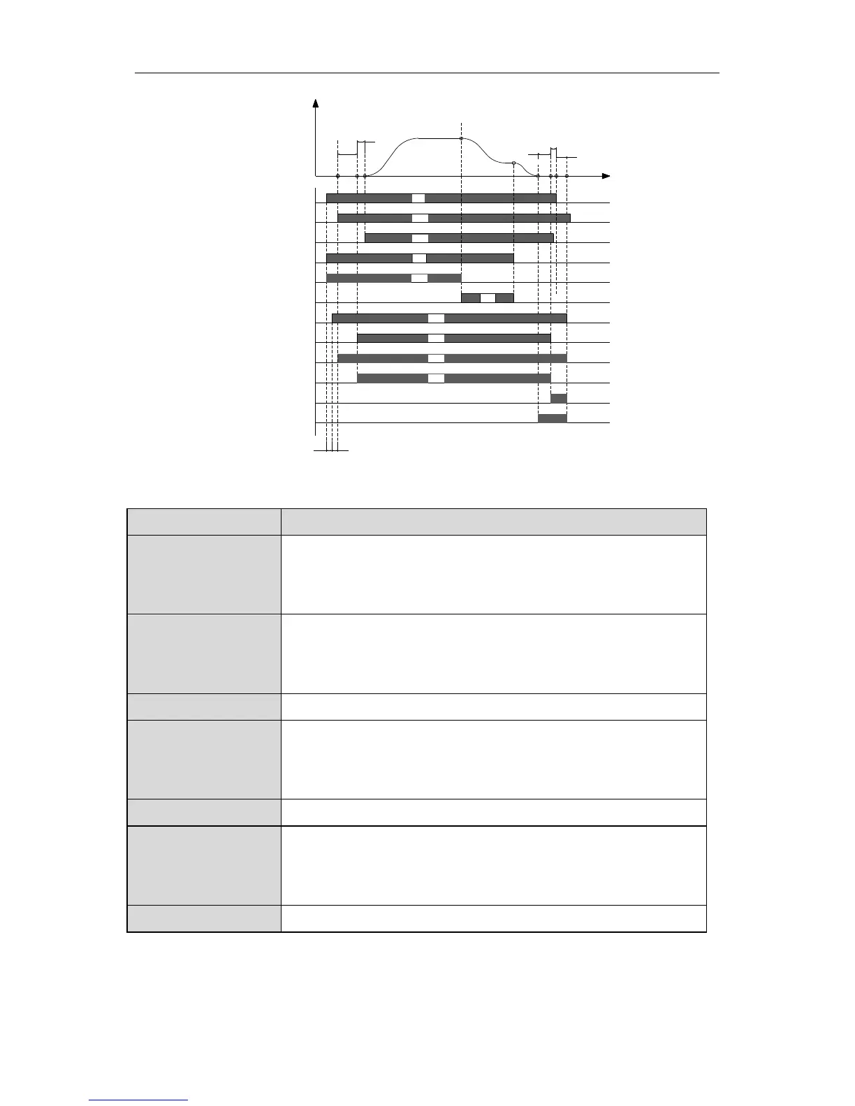
Y1
ON
OFF
OFF
Close out
Zero run
OFFOFF
Figure A.2 Sequence chart of running for Multi-step speed control.
The meanings of T1~T7 are as follows:
Symbol Meanings
T1
The system delay from the time when the inverter receives
running signal to the time when the inverter outputs pull-in
command of contactor.
T2
Waiting delay from the time when the inverter outputs
contactor pull-in command to the time when the inverter
receives contactor feedback signal.
T3 P8.06 (Contacting brake-closing delay time)
T4
Waiting delay from the time when the inverter brake-releasing
output command to the time when the inverter receives
contracting brake feedback signal.
T5 P8.05 (Contacting brake-releasing delay time)
T6
Waiting delay from the time when the inverter outputs closing
brake command to the time when the inverter receives
stopping command from external control.
T7 P8.20 (Inverter stop delay time)
The description of sequence chart:
After inverter receive the running command (FWD) and running speed command
 Loading...