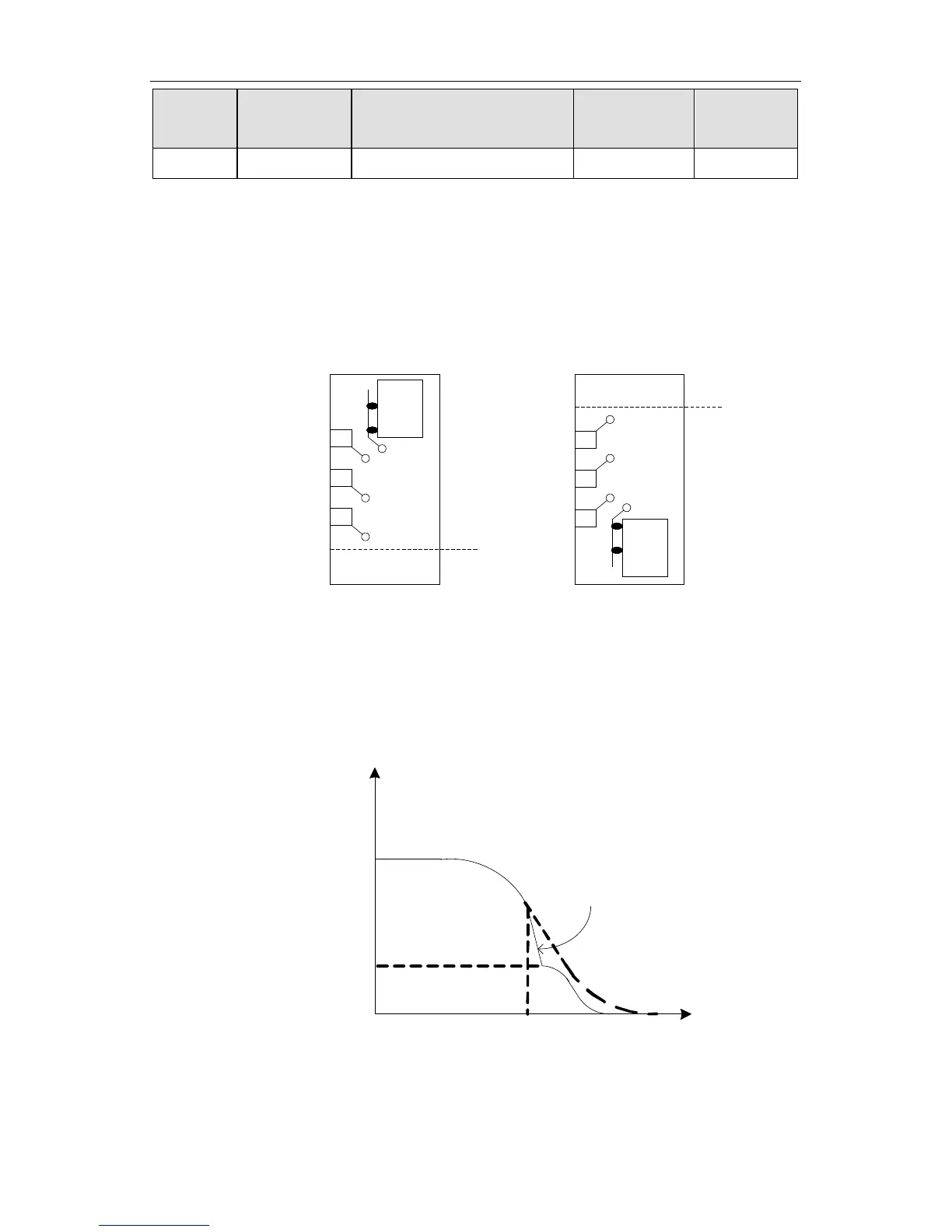
The above function codes will be valid after the forced deceleration switch input is
selected, the effect of forced deceleration is to prevent elevator from top-hitting or
bottom-clashing in the process of up or down running. There is only one group forced
deceleration switch in low speed elevator, and there are two or three groups forced
deceleration switches in the high speed elevator. The installation of sketch map is as
figure 6.8:
Down forcing
decelerating switch 3
Down forcing
decelerating switch 2
Up forcing
decelerating switch 1
Up forcing
decelerating switch 2
Compartments
Up forcing
decelerating switch 3
Up forcing decelerating
switch
Top of well
Top
Down forcing
decelerating switch 1
Down forcing decelerating
switch
Bottom of well
Bottom
Compartments
Figure 6.8 Installation sketch of forced deceleration switch.
For example, when the elevator is running up close to top, forced deceleration switch 3
will act, if the checked running speed is greater than P1.28XP0.02 at this time, elevator
will decelerate at the value of P1.27 to 0, The detailed curve is as follow:
Figure 6.9 Forced deceleration running chart.
Forcing deceleration running conditions:
V
 Loading...