CHV180 series frequency inverter special for elevator Extension card
.85.
7.3.2.2 Terminals and DIP
There are 9 wiring terminals in asynchronous PG card:
+12V COM1
COM1
Figure 7.8 Wiring terminals in asynchronous PG card.
Among them, +12V and COM1 are the power supply output for the encoder; TERA+,
TERA-, TERB+ and TERB- are the input terminal for the encoder; TER-OA, TER-OB
and COM1 are the output terminal for frequency division signal and there is no PE in
the internal of the card, so the user can ground by themselves during use.
The frequency coefficient of asynchronous PG card is determined by the DIP switch on
the card. There are 8 switches and the frequency coefficient is decided by the shown
binary figures that are added by 1. ” 1” on the switch s the low bit and “8” is the high bit.
When the DIP is switched to ON, the bit is valid, reverse it is “0”.
Frequency division coefficient:
Decimal Digit Binary Digit
Frequency Division
Factor
0 00000000 1
1 00000001 2
2 00000010 3
… … …
m … m+1
255 11111111 256
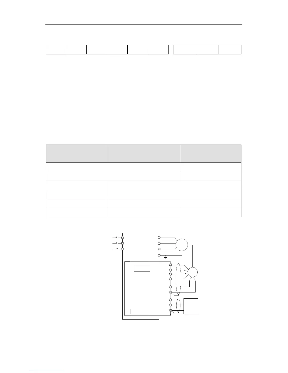
7.3.2.3 Wiring Diagram
T
S
R U
V
W
PE
Potentiometer
Frequency-division
DIP switch
TERA+
+12V
COM1
TER-OA
TERA-
TERB+
TERB-
TER-OB
COM1
36000
RPM
meter
PG
M
Power supply
AC 3PH 380V
50/60Hz
R
S
T
Figure 7.8 PG Card Wiring Diagram.
 Loading...