CHV180 series frequency inverter special for elevator Extension card
.86.
7.3.2.4 Wiring precautions
The signal wire of the PG card should be routed separately from the power lines.
Please select the shield cables as the PG signal wire for the avoidance of encoder
signal.
The shield layer of the encoder cables should be founded with one end (for example,
the PE end of the inverter) for the avoidance of the signal interference.
If the frequency division output of the PG card is connected with the user power supply,
the voltage is less than 24V, otherwise, the PG card may be damaged.
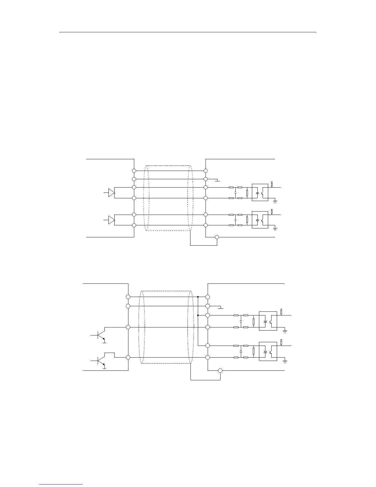
7.3.3 Application Connection
(1) Wiring Diagram of Differential Output Coder
B+
A+
TERB -
TERB +
TERA -
TERA +
COM1
PWR
PE
VCC
0 V
A-
B-
+3.3V
A
B
PG Card
Use shield cable
Differential
output coder
+3.3V
Figure 7.9 Wiring Diagram of Differential Output Coder.
(2) Wiring Diagram of Open Collector Output Coder
TERB -
TERB +
TERA -
TERA +
+3.3V
Open collector
output coder
Use shield cable
PG Card
B
A
+3.3V
OV
OV
B
A
0 V
VCC
PE
PWR
COM1
Figure 7.10 Wiring Diagram of Open Collector Output Coder.
(3) Wiring Diagram of Push-pull Output Coder
 Loading...