Goodrive35 Series Closed-loop Vector Control VFD Installation guide
34
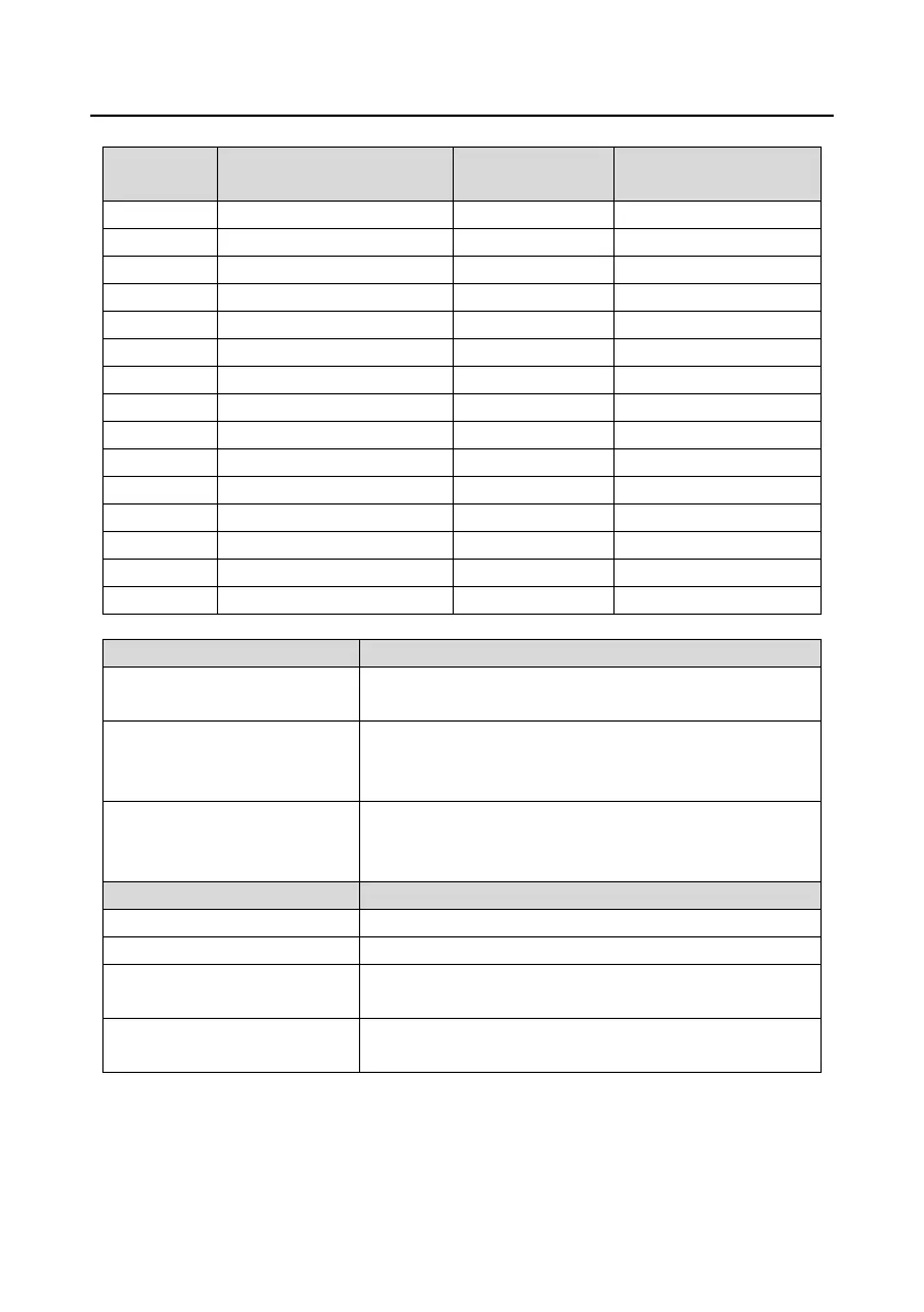
4.4.5.2 Interfaces instruction
CNC system interface
signal
4.4.5.3 Terminal instruction
5 V differential pulse + direction reference signal, Support
400 kHz at maximum
AO+, AO-, BO+, BO-, ZO+, ZO-
Frequency-divided output of encoder pulse signals, 5 V
differential signals
Frequency dividing ratio: 1:1
Alarm output (If use this function, it is necessary to
short-connect Y terminal to +24 V terminal, and remove the
tag between CME and COM terminal)
Encoder power supply, support 5 V±5%, 200mA power
A1+, A1-, B1+, B1-, Z1+, Z1-
The encoder differential input signal, support 400 kHz at
maximum
Difference angle input signal input of UVW encoders (not for
incremental encoders)
Note: Refer to section 4.4.1 for detailed information of AO1, AO2, AI1, AI2, 485 and other terminals.

 Loading...