Goodrive35 Series Closed-loop Vector Control VFD Installation guide
33
Support encoder differential, open collector, and
push-pull pulse reference signal. Pulse reference
signal, default as 5 V input. External current-limiting
resistor is needed when the input voltage is above 10 V
AO+, AO-, BO+, BO-, ZO+ and ZO-
Frequency-divided output of encoder pulse signals, 5 V
differential signals
Frequency dividing ratio: 1:1
Power supply ground of the encoder
Note: Refer to section 4.4.1 for detailed information of AO1, AO2, AI1, AI2, 485 and other terminals.
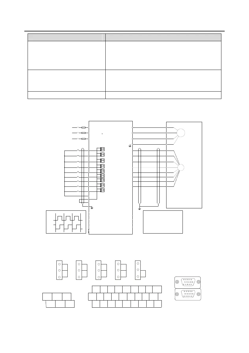
4.4.4.3 Wiring diagram
+24V
PE
COM
S4
S3
S2
S1
HD1
PW
S5
S6
S7
S8
A1-
A1+
COM
PWR
B1+
B1-
Z1+
Z1-
R
S
T
U
V
W
U
V
W
M
3~
PG
AO+
AO-
BO+
BO-
ZO+
ZO-
pulse A
pulse B
A2+
A2-
B2+
B2-
Fault reset
Spindle rotates forward
CNC
PLC
Upper PC
4.4.5 H2 terminal (EC-PG305-05) instruction and the wiring diagram
4.4.5.1 Terminal arrangement
V
AO1 AO2 AI
1
AI 2 485
I
V
I
V
I
V
I ON
J1 J2 J3 J4 J5
S1 S2 S3 S4 HDI AI1 AI2 AI3 +10V
S5 S6 S7 S8 HDO GND AO1 AO2 GND
+24V PW COM COM CME Y1 485+ 485- PE
RO1A RO1B RO1C
RO2A RO2B RO2C
CNC
ENCODER
1
6
11
15
5
10
15
5
10
1
6
11

 Loading...