Goodrive35 Series Closed-loop Vector Control VFD Dimension drawings
260
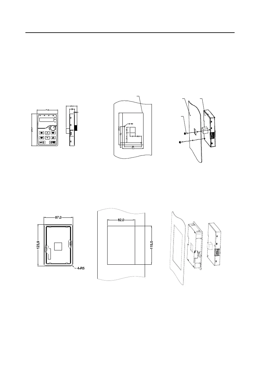
Appendix C Dimension drawings
C.1 What this chapter contains
Dimension drawings of the Goodrive35 are shown below. The dimensions are given in millimeters
and inches.
C.2 Keypad structure
C.2.1 Structure chart
Ho le dimension a nd diagra m for keypad installation w ithout bracket
2-M3x10
combination screw
Dotted frame is the
outline of keypad
Panel
Keypad
C.2.2 Installation bracket
Note: The external keypad can be fix by M3 screws directly or the installation bracket. The installation
bracket for VFDs of 380 V 1.5–30 kW is optional, the installation bracket for VFDs of 380 V 37–315
kW and 660 V 22–630 kW is optional or substitutive by the external standard one.
Keypad bracket
Customer installation dimension
Figure C-1 Installation bracket of the keypad (380 V 1.5–315 kW; 660 V 22–630 kW) (optional)

 Loading...