Goodrive35 Series Closed-loop Vector Control VFD Installation guide
17
a) Wall mounting (for the VFDs of 380 V≤315 kW and the VFDs of 660 V≤350 kW)
b) Flange mounting (for the VFDs of 380 V≤200 kW and the VFDs of 660 V≤220 kW)
c) Floor mounting (for the VFDs of 380 V 220-500 kW and the VFDs of 660 V 250–630 kW)
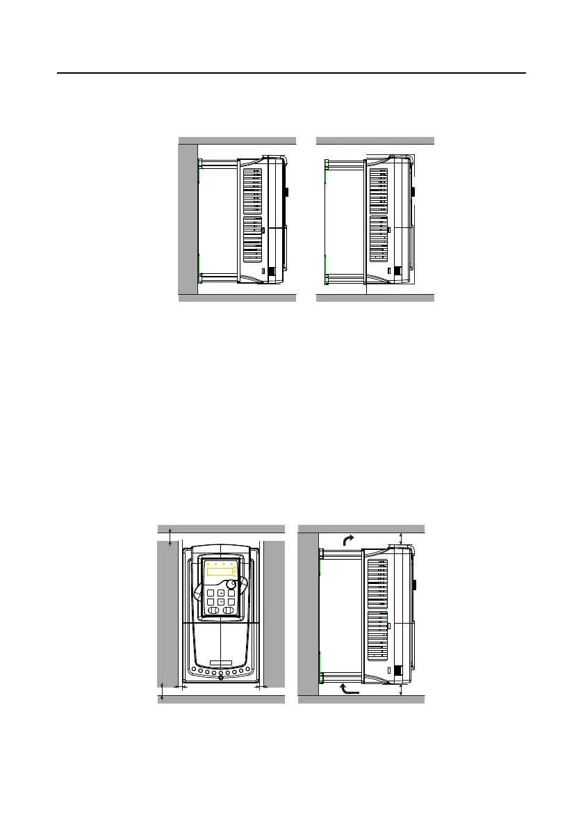
Wall mounting Flange mounting
Figure 4-2 Installation manner
(1) Mark the hole location. The location of the holes is shown in the Appendix C "Dimension drawings".
(2) Fix the screws or bolts to the marked locations.
(3) Put the VFD against the wall.
(4)Tighten the screws in the wall securely.
Note:
1. The flange installation of the VFDs of 380 V 1.5–30 kW need flange board, while the flange
installation of the VFDs of 380 V 37–200 kW and 660 V 22–220 kW does not need.
2. The VFDs of 380 V 220–315 kW and 660 V 250–350 kW need optional bases and there is an input
AC reactor (or DC reactor) and output AC reactor in the base.
4.2.4 Single installation
Figure 4-3 Single installation
Note: The minimum space of B and C is 100mm.

 Loading...