Goodrive35 Series Closed-loop Vector Control VFD Basic operation instruction
166
Detailed instruction of
parameters
HDI high-speed pulse input function
0: Frequency setting input
1–2: Reserved
Lower limit frequency of HDI
Corresponding setting of HDI low
frequency setting
Upper limit frequency of HDI
Corresponding setting of upper limit
frequency of HDI
HDI frequency input filter time
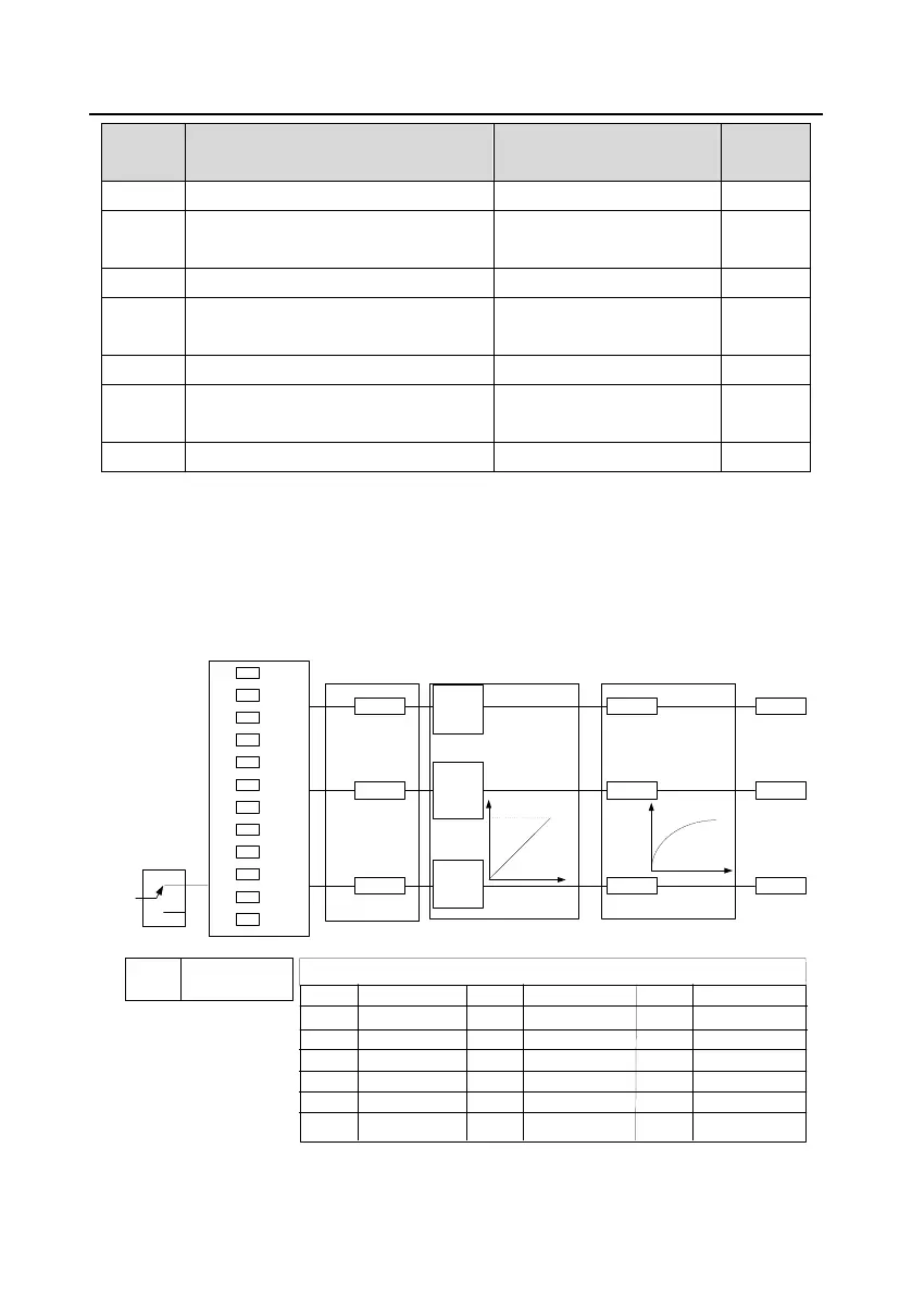
7.10 Analog output
Goodrive35 series VFDs have 2 analog output terminals (0–10 V or 0–20mA) and 1 high speed pulse
output terminal. Analog output signal can be filtered and the maximum and minimum values can be
adjusted. The analog output signals can be proportional to motor speed, output frequency, output
current, motor torque, motor power, etc. 100% of the output current is relative to 2 times of the rated
current of the VFD.
0
1
2
3
.
.
.
.
.
.
19
20
P06.14
P06.15
P06.16
AO1
AO2
HDO
P06.17
P06.18
P06.19
P06.20
P06.22
P06.23
P06.24
P06.25
P06.27
P06.28
P06.29
P06.30
P06.26
P06.21
P06.31
(default value is 0)
(default value is 0)
(default value is 0)
P06.00
(HDO output type selection)
0 Running frequency 1 Set frequency
3 Running rotation speed 4
Output current (relative to the
VFD)
6 Output voltage 7 Output power
9 Output torque 10 Analog AI1 input value
12 Analog AI3 input value 13 HDI input value
15
MODBUS communication
setting 2
16
PROFIBUS communication
setting 1
2 Ramp given frequency
5
Output current (relative to the
motor)
8 Set torque
11 Analog AI2 input value
14
MODBUS communication
setting 1
17
PROFIBUS communication
setting 1
18
Torque current (relative to the
nominal current of the motor)
19
Exciting current (relative to the
nominal current of the motor)
20 Reserved
0
1
P06.00
0: open collector high speed
pulse output
1: open collector output
P06.01、P06.02、P06.03、P06.04 output selection
Analog output curve setting
Analog output selection Analog output filter setting

 Loading...