Goodrive35 Series Closed-loop Vector Control VFD Installation guide
37
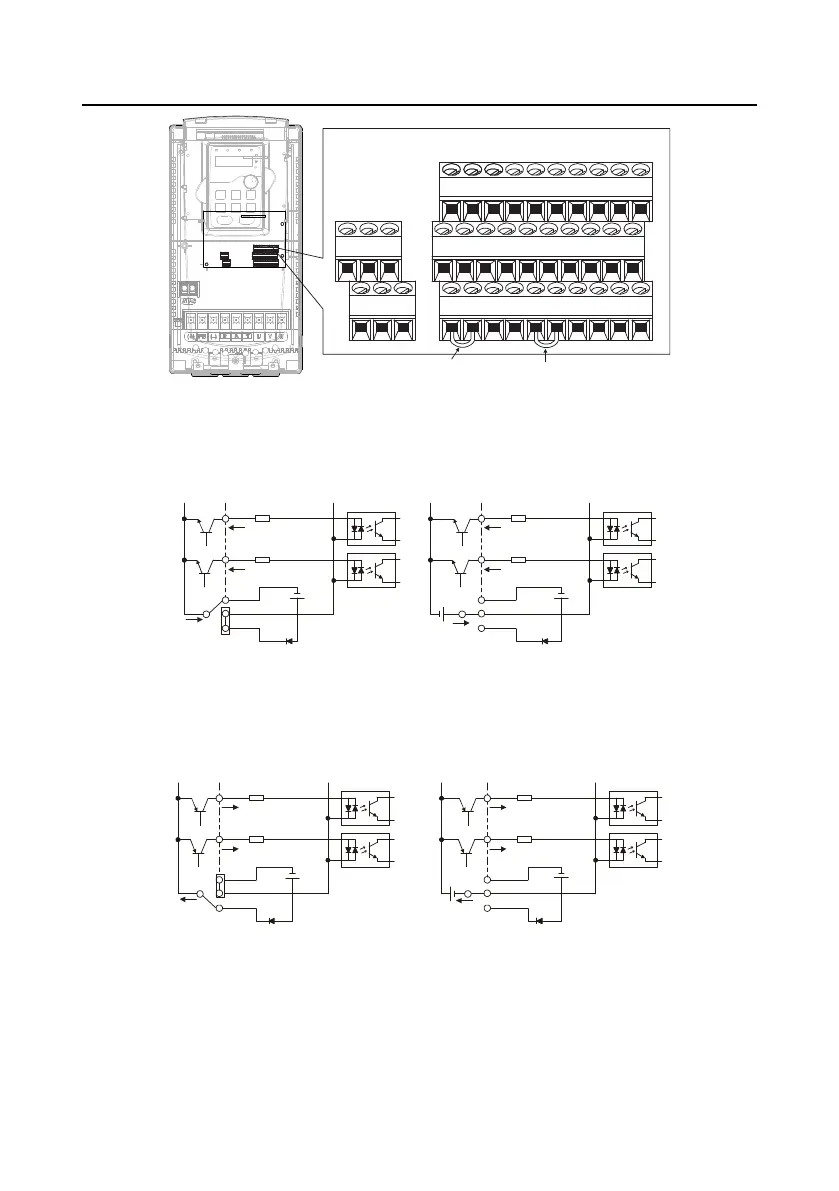
U-type shorting
bar of COM and
CME
U-type shorting
bar of +24V and
PW
Figure 4-21 U-shaped contact tag
If the signal is from NPN transistor, please set the U-shaped contact tag between +24 V and PW as
below according to the used power supply.
S1
S2
COM
PW
+ 24V
COM
+ 24V
Internal power supply (NPN mode)
S1
S2
COM
PW
+ 24V
COM
+ 24V
+ 24V
External power supply (NPN mode)
Figure 4-22 NPN modes
If the signal is from PNP transistor, please set the U-shaped contact tag as below according to the
used power supply.
S1
S2
COM
PW
+ 24V
COM
+24V
S1
S2
COM
PW
+ 24V
COM
+24V
Internal power supply (PNP mode)
External power supply (PNP mode)
Figure 4-23 PNP modes
4.5 Wiring protection
4.5.1 Protecting the VFD and input power cable in short-circuit situations
Protect the VFD and input power cable in short circuit situations and against thermal overload.

 Loading...