Goodrive35 Series Closed-loop Vector Control VFD Installation guide
27
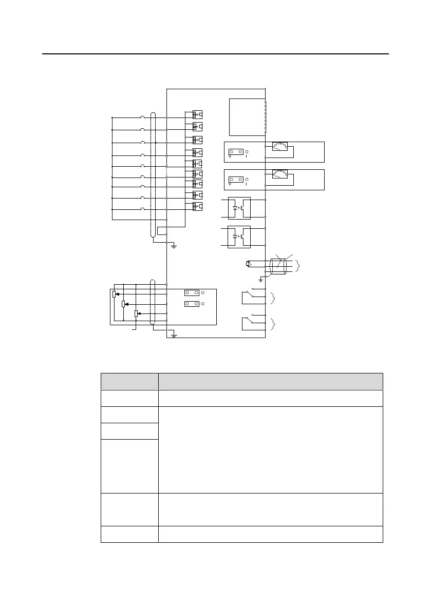
4.4 Standard wiring (control circuit)
4.4.1 Wiring diagram of basic control circuit
External
extension
card
(optional)
Standard
Analog output
Analog output
Multi-function input terminal 1
Multi-function input terminal 2
Multi-function input terminal 3
Multi-function input terminal 4
Multi-function input terminal 5
Multi-function input terminal 6
Multi-function input terminal 7
Multi-function input terminal 8
High-speed pulse input collection
Power supply
High-speed pulse output
and electrode open output selection
Open collector output
Shield layer
Twisted pair
Y1
- ()10V external
Open collector input
S1
S2
S3
S4
S5
S6
S7
S8
HDI
COM
PW
J1
J2
AO1
GND
0–10V/0–20mA
0–10V/0–20mA
AO2
GND
HDO
CME
CME
RS485
communication
485+
485-
GND
PE
RO1A
RO1B
RO1C
RO2A
RO2B
RO2C
RO1
RO2
Profibus
DB9 plug
+24V
PE
J3
J4
AI1
AI2
AI3
GND
V
V
I
I
PE
+10V
J5
Multi-function
analog input
Goodrive35 VFD
Figure 4-20 Wiring of control circuit
1. Input range: AI1/AI2 voltage and current can be chosen: 0–10
V/0–20mA; AI1 can be shifted by J3 while AI2 can be shifted by
J4; AI3: -10 V–+10 V
2. Input impedance: voltage input: 20kΩ; current input: 500Ω
3. Resolution: the minimum one is 5m V when 10 V corresponds
to 50 Hz
4. Deviation ±1%, 25°C
+10 V reference null potential
1. Output range: 0–10 V or -20–20mA; The voltage or the

 Loading...