Goodrive35 Series Closed-loop Vector Control VFD Installation guide
22
Note:
1. The fuse, DC reactor, brake unit, brake resistor, input reactor, input filter, output reactor, output filter
are optional parts. Please refer to Appendix D "Optional peripheral accessories" for detailed
information.
2. P1 and (+) are short circuited in factory, if need to connect with the DC rector, please remove the
contact tag between P1 and (+).
3. When connecting the brake resistor, take off the yellow warning label marked with (+) and (-) on the
terminal bar before connecting brake resistor wire, otherwise, poor contact will occur.
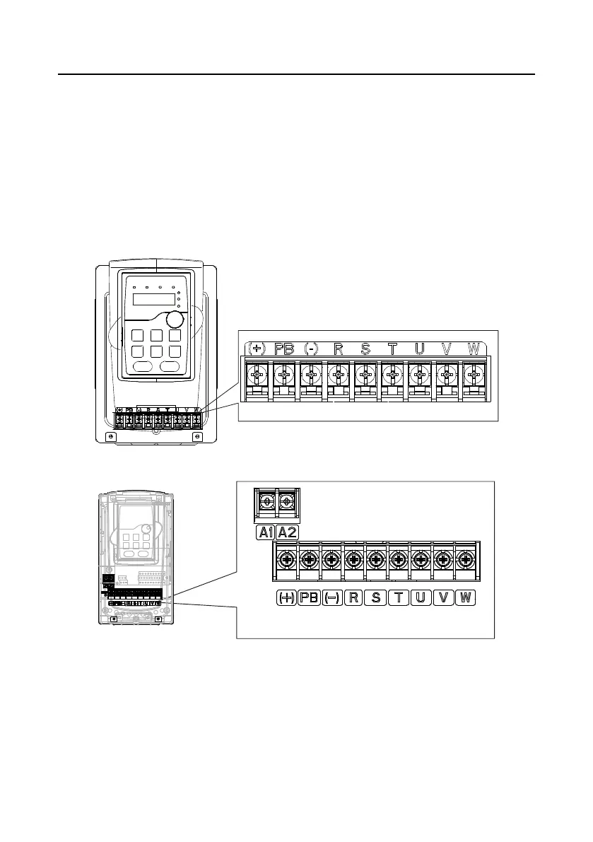
4.3.2 Terminals figure of main circuit
Figure 4-9 Terminals of main circuit for the VFDs of 380 V 1.5–2.2 kW
Figure 4-10 Terminals of main circuit for the VFDs of 380 V 4–5.5 kW

 Loading...