Goodrive35 Series Closed-loop Vector Control VFD Basic operation instruction
197
The steps of (1)–(4) are the same as the 4 steps in close-loop vector control mode. After the 4 steps,
the control requirements can be met.
(5) Set P21.00=0021 to enable the positioning. The signal is only connected with S8. Set P05.08=43
and P21.17, P21.11, P21.12 and P21.21. If the operation speed is big or the setting placement is too
small, the positioning deceleration time is invalid and it will enter into the direct deceleration mode.
(6) Cycle positioning operation
The motor will keep on the current position after positioning. Set group P05. If the terminal receives
the enabling signal, the motor will operate at the setting speed in speed mode, after receiving
photoelectric switch signal, it will position again.
(7) Positioning retention
During the positioning, the position loop gain is P21.03, but after positioning, it is P21.02. Adjust
P03.00, P03.01, P20.05 and P21.02 to keep the position and avoid vibration.
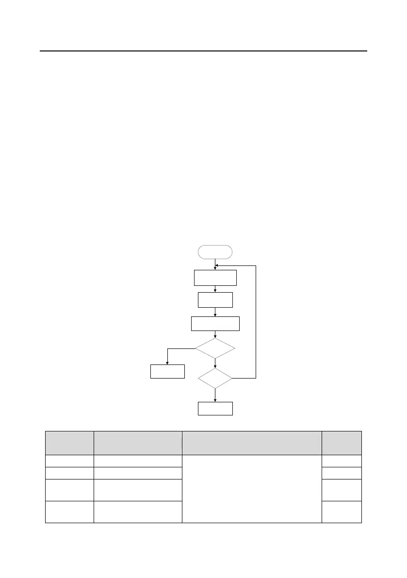
7.17 Fault solutions
Goodrive35 series VFDs provide sufficient fault procedure information for the convenience of user’s
application.
In running
Fault occurs and the
keypad displays the
fault code
Look up the fault
reason according
to the fault code
According to
P07.33~P07.40 to
estimate the best reason
Rerunning
Normal running
Settle the fault
consult INVT
Y
N
N
Y
Relative parameters list:
Detailed instruction of parameters
0: No fault
1: Inverter unit phase protection (OUt1)
2: Inverter unit V phase protection
(OUt2)
3: Inverter unit W phase protection
Type of the last but one
fault
Type of the last but two
fault

 Loading...