Goodrive35 Series Closed-loop Vector Control VFD Product overview
8
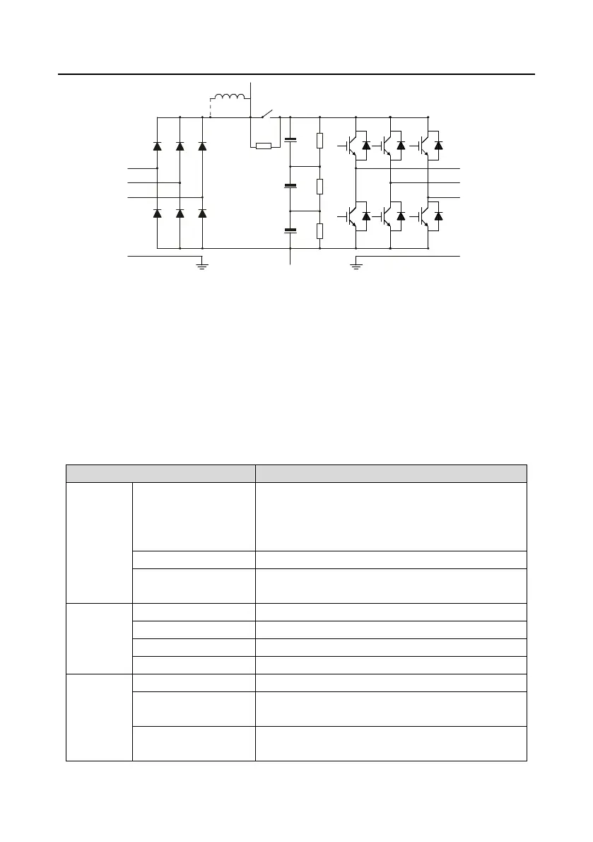
R
S
T
PE
U
V
W
(+)
(-)
P1
PE
DC reactor
Figure 3-3 The simplified main circuit diagram (VFDs of 660 V)
Note:
1. The VFDs of 380 V (≥37 kW) supports external DC reactors and external brake units, but it is
necessary to remove the copper tag between P1 and (+) before connecting. DC reactors and brake
units are optional.
2. The VFDs of 380 V (≤30 kW) supports external brake resistors which are optional.
3. The VFDs of 660 V supports external DC reactors and external brake units, but it is necessary to
remove the copper tag between P1 and (+) before connecting. DC reactors and brake units are
optional.
3.3 Product specification
AC 3PH 380 V (-15%)–440 V (+10%)
Rated voltage: 380 V
AC 3PH 520 V (-15%)–690 V (+10%)
Rated voltage: 660 V
Refer to section 3.6 "Rated values"
50 Hz or 60 Hz
Allowed range: 47–63 Hz
Refer to section 3.6 "Rated values"
Refer to section 3.6 "Rated values"
Technical
control
feature
Asynchronous motor and permanent magnet
synchronous motor
Asynchronous motor 1: 200 (SVC) synchronous motor 1:
20 (SVC) 1: 1000 (VC)

 Loading...