Goodrive35 Series Closed-loop Vector Control VFD Installation guide
36
Pulse reference and output
interface signal
Sin/cos encoder
interface signal
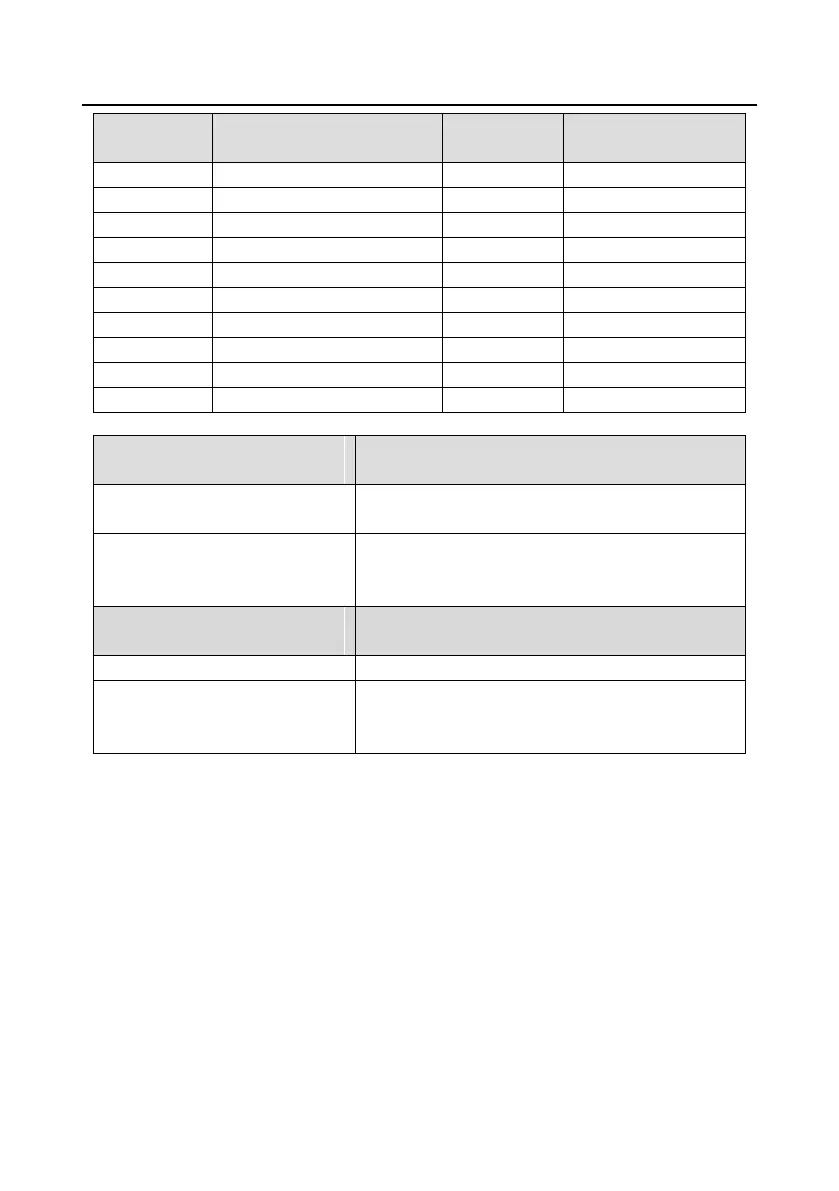
4.4.6.3 DB15 pin function instruction
Name of upper layer terminal
(pulse reference interface)
5 V differential quadrature pulse reference signal,
support 400 kHz at maximum
AO+, AO-, BO+, BO-, ZO+, ZO-
Frequency-divided output of encoder pulse signals, 5 V
differential signals
Frequency dividing ratio: 1:1
Name of lower layer terminal
(sin/cos encoder interface)
Encoder power, can provide 5 V±5%, 200mA.
A+, A-, B+, B-, C+, C-, D+, D-, R+,
R-
Sin/cos encoder signal input, support
SINA/SINB/SINC/SIND 0.8–1.2 Vpp, SINR 0.2–0.85
Vpp, 200 kHz at maximum
4.4.7 Input/output signal connection diagram
Use U-type tag to set the NPN/PNP mode and internal/external power sources. The default setting is
NPN internal mode.

 Loading...