Goodrive35 Series Closed-loop Vector Control VFD Basic operation instruction
196
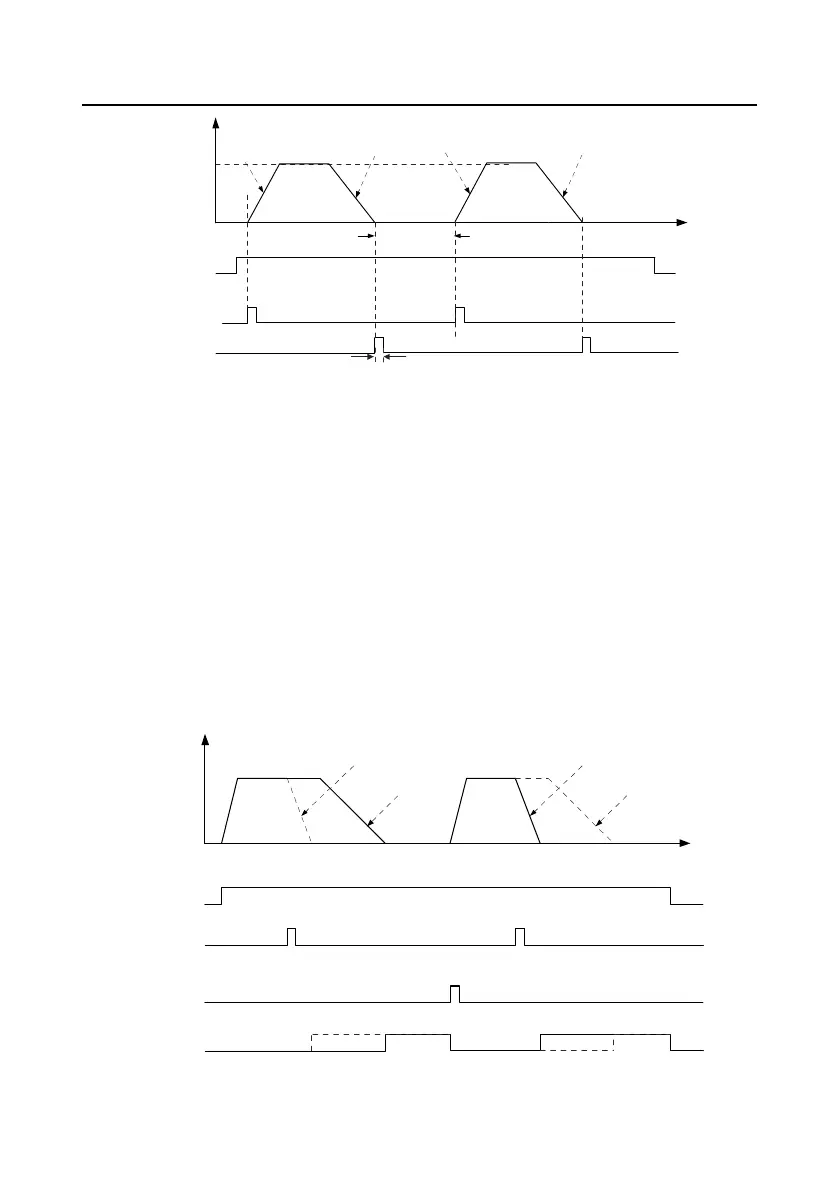
Frequency
Positioning
speed
Running
command
P21.22
Terminal of
enabling signal
Positioning
finished signal
P21.20
Time
P21.25
P21.20
P21.21
P21.21
The steps of (1)–(4) are the same as the 4 steps in close-loop vector control mode. After the 4 steps,
the control requirements can be met.
(5) Set P21.00=0011 and set P21.17, P21.11, P21.12, P21.18, P21.19, P21.20 and P21.21 according
to actual needs.
(6) Single positioning operation
Set P21.16.bit1=0, and the motor will set as step (5) and keep on the positioning place.
(7) Cycle positioning operation
Set P21.16.bit1=1 to enable the loop positioning which includes continuous mode and repeated mode.
The operation is also available by terminals function.
6. Photoelectric switch positioning
Photoelectric switch positioning is to position in the closed-loop vector control mode.
Frequency
Time
Direct deceleration
positioning
Direct deceleration
positioning
Constant + DEC
positioning
Constant + DEC
positioning
Running
command
Photoelectric
switch arrival
signal
Cycle
positioning
enabling signal
Positioning
finished
signal

 Loading...