MK-100151 Rev. A
27
ENGLISH
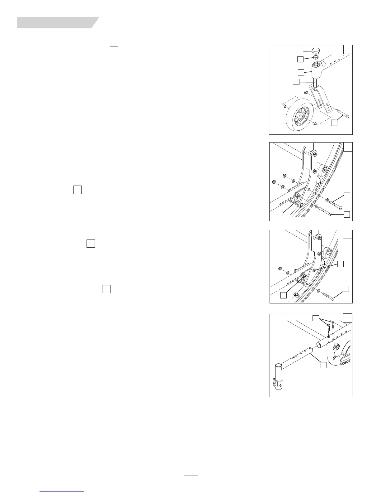
W. CASTER/FORK ASSEMBLY
1. Installation
a. Remove dust cover (A) from caster housing. Pry cover off using a back and forth motion.
b. Caster assembly holds one nut (B) and one washer (immediately below the nut). Remove nut and
washer.
c. Insert caster stem (D) into caster housing (C) and place washer on stem.
d. Replace nut (B) on caster stem and tighten until all play is removed; then loosen approximately 1/8 turn,
allowing for free rotation.
e. Replace dust cover to caster housing.
2. Height Adjustment
a. Loosen and remove bolt (E).
b. Set axle at desired height using pre-set holes in the fork.
c. Replace and tighten bolt.
d. Repeat on other side.
NOTE–
The frame must be kept horizontal when height is adjusted. Refer to matrix in the ordering guide
for proper setting. Refer to Section S-7 for rear axle height adjustment.
X. FRAME DEPTH
1. Back adjustment
a. Remove the screws (F & H) from the back mounting plate (G) on both sides of the chair.
b. Slide the backrest along the seat rail to the same position on both sides.
c. Replace and tighten the screws (F & H) to lock in the position on both sides of chair.
IMPORTANT NOTE–
The adjustment on each side of the chair should be exactly equal.
NOTE–
Use a torque setting of 120 in.-lbs. When setting-up back depth adjustment.
2. Back angle adjustment
a. Remove the screw(F) and loosen H) from the back mounting plate (G) on both sides of the chair.
b. Adjust the backrest to the same position on both sides, using one of the three adjustment holes
shown.
c. Tighten the screws (F & H) to lock in the position on both sides of chair.
3. Hanger Receiver Adjustment
a. Loosen and remove both Socket head screws (I) from the seat rail.
b. Slide the hanger receiver (J) in the seat rail to the desired position.
c. Replace and tighten the socket head screws.
d. Repeat this process on the other side.
IMPORTANT NOTE–
These adjustments may also require re-positioning the carriage over the base frame,
refer to matrix in the ordering guide for recommended location.
IMPORTANT NOTE–
The adjustment on each side should be exactly equal.
NOTE–
Use a torque setting of 120 in.-lbs. When setting-up hanger receiver.
64
65
66
67
IX. DEALER SERVICE & ADJUSTMENT
64
A
B
E
D
C
65
66
67
F
G
H
I
J
F
G
H