MINI and MIX Series I/O modules/Modbus
version 1.3 www.gc5.pl Page 14 / 73
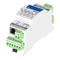
• The power LED is ON (green) when the module runs properly.
• Communication LED is ON (orange) for 20 ms after sending each message.
If the module receives/sends a lot of messages LED can be lit continuously.
• LEDs indicate the status of the Universal Inputs are lit when resistance connected to
the input is less than 5 kΩ (Dry Contact input is active).
WARNING! The LED also lights up when voltage connected to the input has a very low
potential.
• LEDs indicate the status of the digital inputs are lit when the input is active.
• LEDs indicate the status of the analog outputs are lit when output voltage or PWM
factor is different from 0.
• LEDs indicate the status of the digital outputs are lit when output is enabled.
1.9 Grounding and shielding
In most cases, IO modules will be installed in an enclosure along with other devices which
generate electromagnetic radiation. Relays, contactors, transformers, motor invertors etc.
are the examples of these devices. This electromagnetic radiation can induce electrical
noise into both power and signal lines, as well as direct radiation into the module causing
negative effects on the system. Appropriate grounding, shielding and other protective steps
should be taken at the installation stage to prevent these effects. These protective steps
include control cabinet grounding, cable shield grounding, protective elements for
electromagnetic switching devices, correct wiring as well as consideration of cable types
and their cross sections.
1.10 RS485 network termination
Transmission line effects often present a problem on data communication networks. These
problems include reflections and signal attenuation.
To eliminate the presence of reflections from the end of the cable, the cable must be
terminated at both ends with a resistor across the line equal to its characteristic
impedance. The both ends must be terminated since the direction of propagation is
bidirectional. In the case of an RS485 twisted pair cable this termination is typically 120 Ω.