MINI and MIX Series I/O modules/Modbus
version 1.3 www.gc5.pl Page 21 / 73
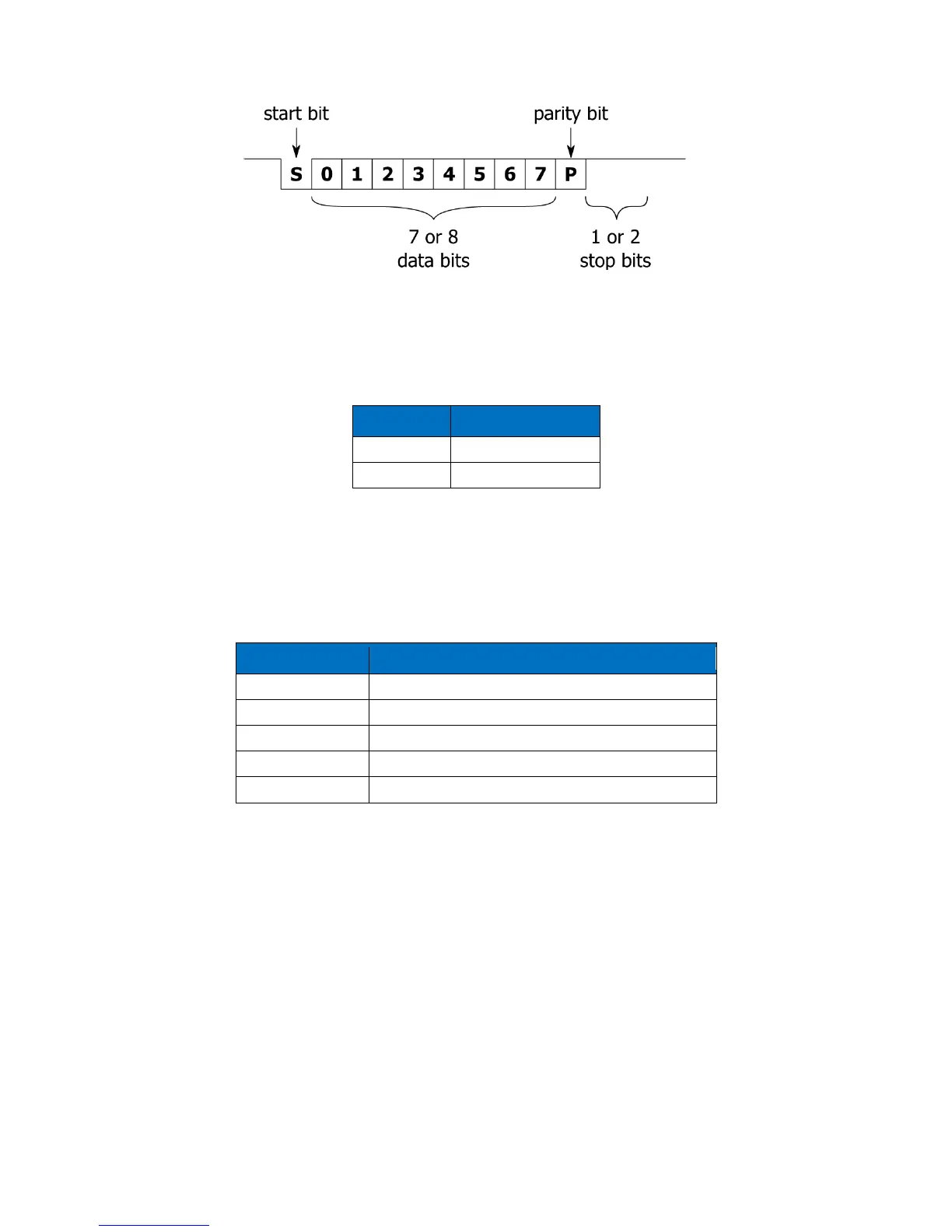
Figure 17 Modbus message frame
2.13 Data bits (40138)
Number of data bits transmitted in a single byte is determined according to the following
table:
Table 11 Data bits
2.14 Parity bit (40139)
Each byte of data being transferred may have additional protection as a parity bit added
before stop bit (bits).
The method of calculating parity bit determines the table below:
Table 12 Parity bit
2.15 Response delay time (40140)
The value of this 16-bits register determines the number of milliseconds to wait before the
unit answers the question. This time is used to extend the interval between question and
answer. The default value of 0 means no delay (the answer is sent once during the 3.5
character required by the protocol Modbus RTU).
2.16 Watchdog time (40141)
This 16-bits register specifies the time in seconds to watchdog reset. If module does not
receive any valid message within that time, all Digital and Analog Outputs will be set to