MINI and MIX Series I/O modules/Modbus
version 1.3 www.gc5.pl Page 20 / 73
2.8 Hardware_version (30130)
This 16-bits register contains the module hardware version multiplied by 10.
2.9 MAC_address (30131)
This 32-bits register contains the module MAC address information.
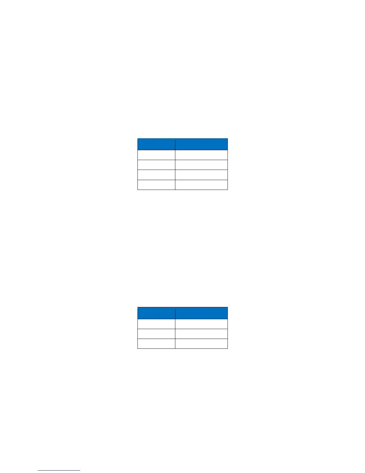
2.10 Device actions (40001)
Setting register 40001 according to the table below will enable 1 of 4 available actions: reset
module, reload settings, set to default and enter bootloader.
Table 9 Device actions
2.11 Baud rate (40136)
When sections 1, 2 and 3 of S3 switch are in off position, baud rate is determined in
accordance with this register. Baud rate is determined by the following formula:
Baud rate = Register value • 10
2.12 Stop bits (40137)
Number of stop bits is determined on the basis of this register in accordance with the
following table:
Table 10 Stop bits
*Bit no 8 activates RS485 biasing resistors in order to pull-up voltage on the RS485 bus.
When the bit no 8 is true (bit 8 = 1) then RS485 biasing resistors are activated. The function
is only available in MINI modules with a hardware version >= 2.0
The biasing resistors are useful in case when iSMA modules are connected with a third part
devices with the same RS485 bus and communication errors appears on the network.
WARNING! The only one single device in the network can have biasing resistors activated !