Table of contents
1 Introduction ................................................................................................................................................ 5
1.1 Revision history .................................................................................................................................................... 5
1.2 Safety rules............................................................................................................................................................ 6
1.3 .Technical specifications .................................................................................................................................... 7
1.4 Summary table for all modules ......................................................................................................................... 9
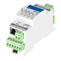
1.5 Dimension ........................................................................................................................................................... 11
1.6 Power supply connection ................................................................................................................................ 12
DC power connection.....................................................................................................................................................12
AC power connection .....................................................................................................................................................12
1.7 Connecting the communication bus (RS485) ............................................................................................. 12
1.8 LED Indicators ................................................................................................................................................... 13
1.9 Grounding and shielding .................................................................................................................................. 14
1.10 RS485 network termination ............................................................................................................................ 14
1.11 Setting Module Address on Modbus Network ............................................................................................ 15
1.12 Baud rate selection ........................................................................................................................................... 15
1.13 Protocol selection ............................................................................................................................................. 16
1.14 Restoring the default settings ........................................................................................................................ 16
1.15 Default Settings ................................................................................................................................................. 17
2 Configuration registers ........................................................................................................................... 18
2.1 Firmware version and module type (30001) ............................................................................................... 18
2.2 Module address (30002) ................................................................................................................................. 18
2.3 Baud rate and protocol (30003) ..................................................................................................................... 19
2.4 Counter of received messages (30004) ....................................................................................................... 19
2.5 Counter of error messages (30006) .............................................................................................................. 19
2.6 Counter of sent messages (30008) .............................................................................................................. 19
2.7 Up time (30012) ................................................................................................................................................ 19
2.8 Hardware_version (30130) .............................................................................................................................. 20
2.9 MAC_address (30131) ..................................................................................................................................... 20
2.10 Device actions (40001) .................................................................................................................................... 20
2.11 Baud rate (40136) ............................................................................................................................................. 20
2.12 Stop bits (40137)............................................................................................................................................... 20
2.13 Data bits (40138) .............................................................................................................................................. 21
2.14 Parity bit (40139) ............................................................................................................................................... 21
2.15 Response delay time (40140) ......................................................................................................................... 21
2.16 Watchdog time (40141) ................................................................................................................................... 21
3 Local I/O ................................................................................................................................................... 23
3.1 Universal Inputs connections ......................................................................................................................... 23
Connection of Universal Input to measure voltage 0 – 10V ..................................................................................23
Connection of Universal Input to measure current 0 – 20 mA .............................................................................23
Connection of Universal Input to measure temperature ........................................................................................24
Connection of Universal Input as a Digital Input (Dry Contact) .............................................................................24
3.2 Universal Inputs MODBUS Registers ............................................................................................................ 25
Status of Universal Inputs working as Digital Inputs (30017) ...............................................................................25
Universal Input measure voltage (current) 1 - 8 (30071, 30073, 30075, 30077, 30079, 30087, 30089, 30091)
25
Universal Input measure temperature 1 - 8 (30072, 30074, 30076, 30078, 30080, 30095, 30097, 30099) 25
Universal Input measure resistance 1 - 8 (30103, 30104 – 30117, 30118) .......................................................25
Universal Input configuration 1 - 8 (40151 – 40158) ..............................................................................................25
Filter time constant of the Universal Input 1 - 8 (40159 – 40166) .......................................................................26
Resolution of the universal inputs (40167) ...............................................................................................................26
3.3 Digital Inputs Connections .............................................................................................................................. 27
Connection of Digital Input (Dry Contact) ..................................................................................................................27