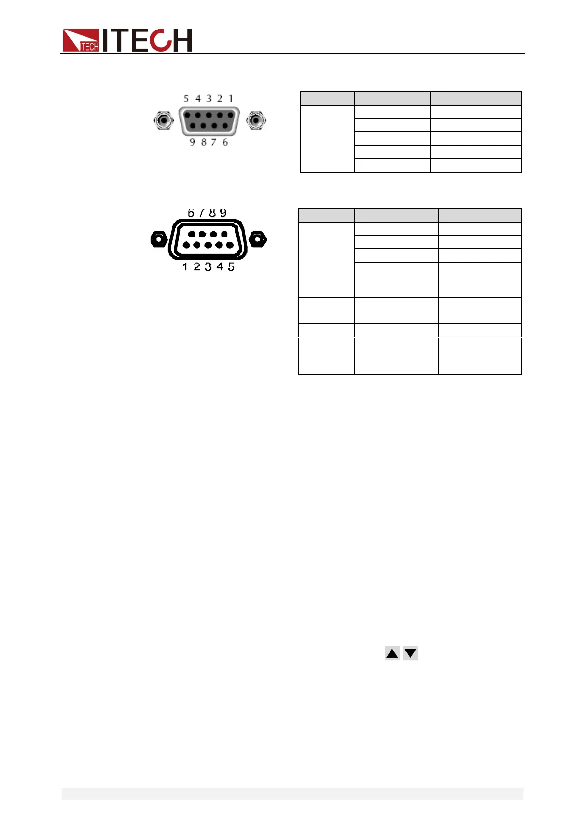
Digital function selection:
The level of SYSTEM I/O interface on the rear panel is TTL level. The interface
can be divided into the following three functional modes:
⚫ Trigger function: Pin 1 can be used as the external trigger terminal of the
power supply. For details, refer to 3.9 Triggering Function.
⚫ Ext On / Off function: Pin 2 can be used for controlling output state of the
power supply.
⚫ DIGio / RIDFi function: Pins 3 and 4 are multiple terminals, which can be
used as the common digital I/O interfaces and read and control the output
terminal state through communication command. Or, they can be used for
indicating power supply fault.
When the multiple terminals are used, select the terminal function mode. Refer
to the steps below:
1. Press the [Menu] key to enter the Menu Configuration page.
2. Select “Config > Conf2” to enter to Configuration Menu interface.
3. Select the “Digital Function” functions by the key. Press the right
soft key corresponding to this parameter to select DIGio or RIDFi mode.
⚫ IT6411/IT6431/IT6432/IT6433/IT6411S/IT6432S