Quick Reference
Copyright © Itech Electronic Co., Ltd. 7
2 Remote sense terminal, the output terminal and DVM terminal(CH1)
3 Remote sense terminal, the output terminal and DVM terminal(CH2)
6 USB communication interface
7 LAN communication interface
8 GPIB communication interface
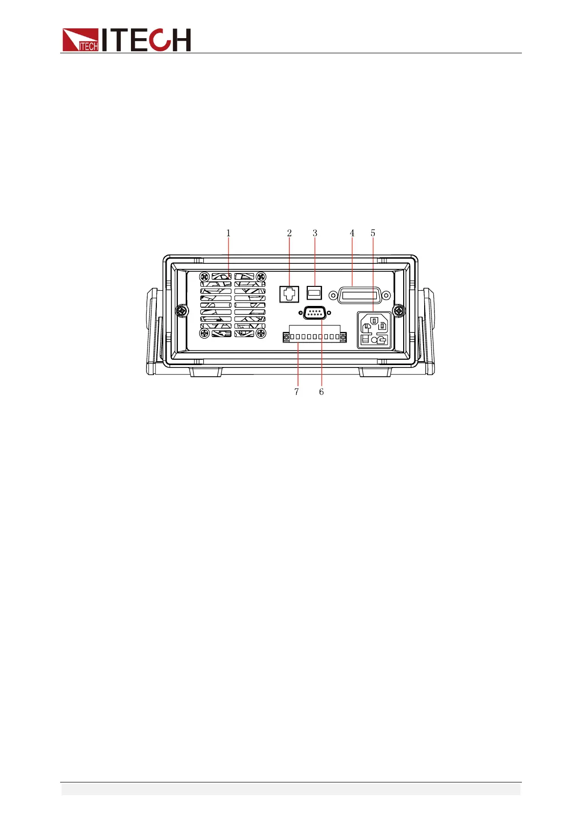
⚫ IT6431/IT6432/IT6433 rear panel.
2. LAN communication interface
3. USB communication interface
4. GPIB communication interface
7. Remote sense terminal, the output terminal and DVM terminal
1.6 Menu at a Glance
Menu configuration interface
Press the [Menu] soft key to enter the Menu configuration interface which
comprises 7 functional icons. You can select these functional icons by the arrow
keys or knob and press OK to confirm. The Menu configuration interface is
shown as follows.