Basic Operation
Pins Name Type Description
4 GND Ground Ground terminal.
5 V_Monitor Analog out Voltage monitor signal. This pin gen-
erates a voltage of 0 V to 10 V to
monitor an input voltage of 0 V to the
maximum rated value.
6 I_Monitor Analog out Current monitor signal. This pin gen-
erates a voltage of 0 V to 10 V to
monitor an input current of 0 V to the
maximum rated value.
7 +10V Analog out The 10V reference voltage output by
the instrument can be connected to
a resistance subdivision for analog
control.
8 Input1 Analog in Set the input setting value.
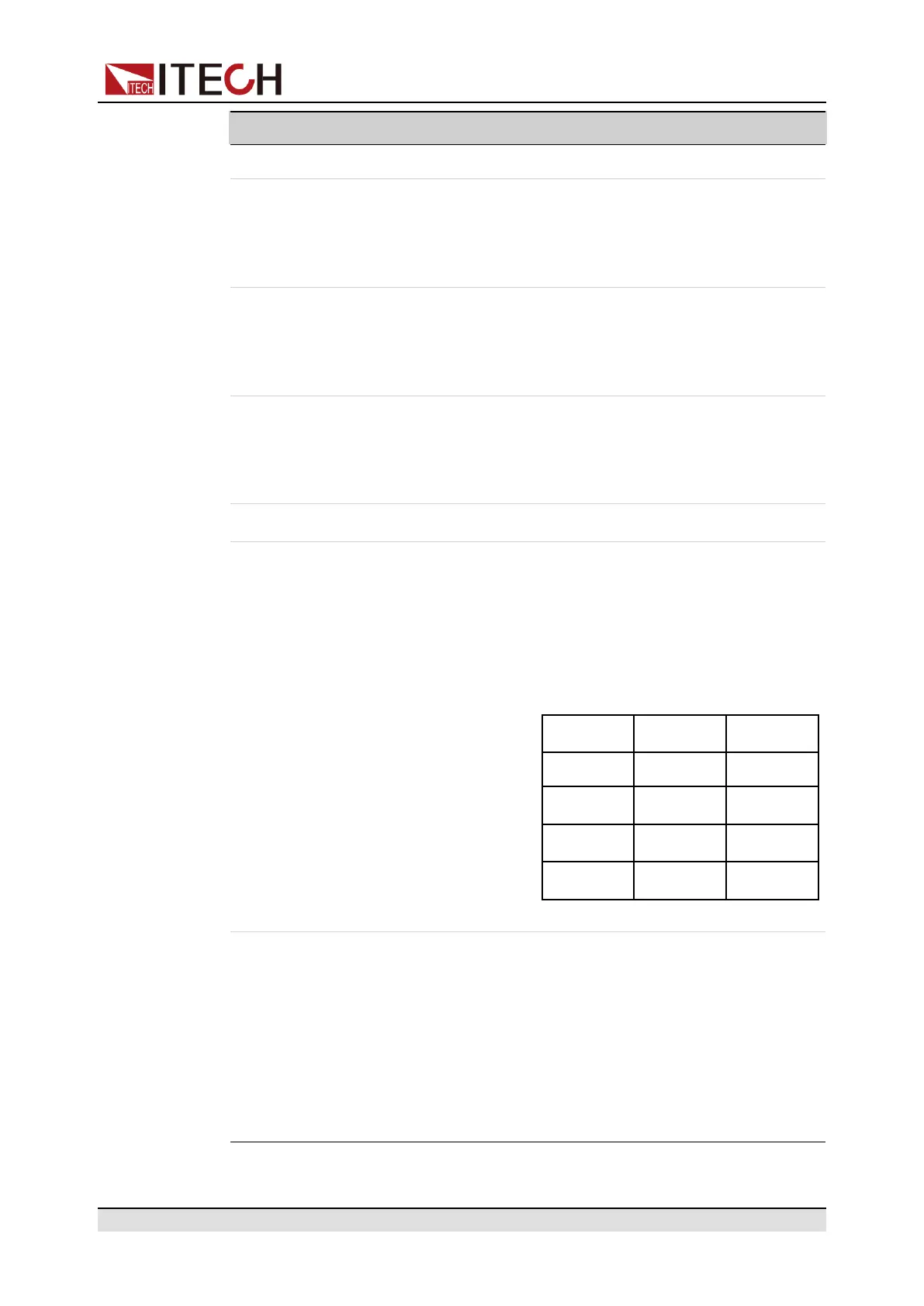
9 Input2 Analog in Set the basic mode of the load.
When the input voltage of the pin is ≤
1V, it is low level. When the input
voltage is ≥ 3V, it is high level. Set
the load mode with the input voltage
and level combination of the Input3:
Input2 Input3 Mode
Low Low CC
Low High CV
High Low CW
High High CR
10 Input3 Analog in Set the basic mode of the load.
When the input voltage of the pin is ≤
1V, it is low level. When the input
voltage is ≥ 3V, it is high level. Set
the load mode with the input voltage
and level combination of the Input2:
For detailed mode definition, refer to
Input2 description.
Copyright © Itech Electronic Co., Ltd.
99
 Loading...