Quick Start
Copyright © ITECH Electronic Co., Ltd. 16
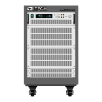
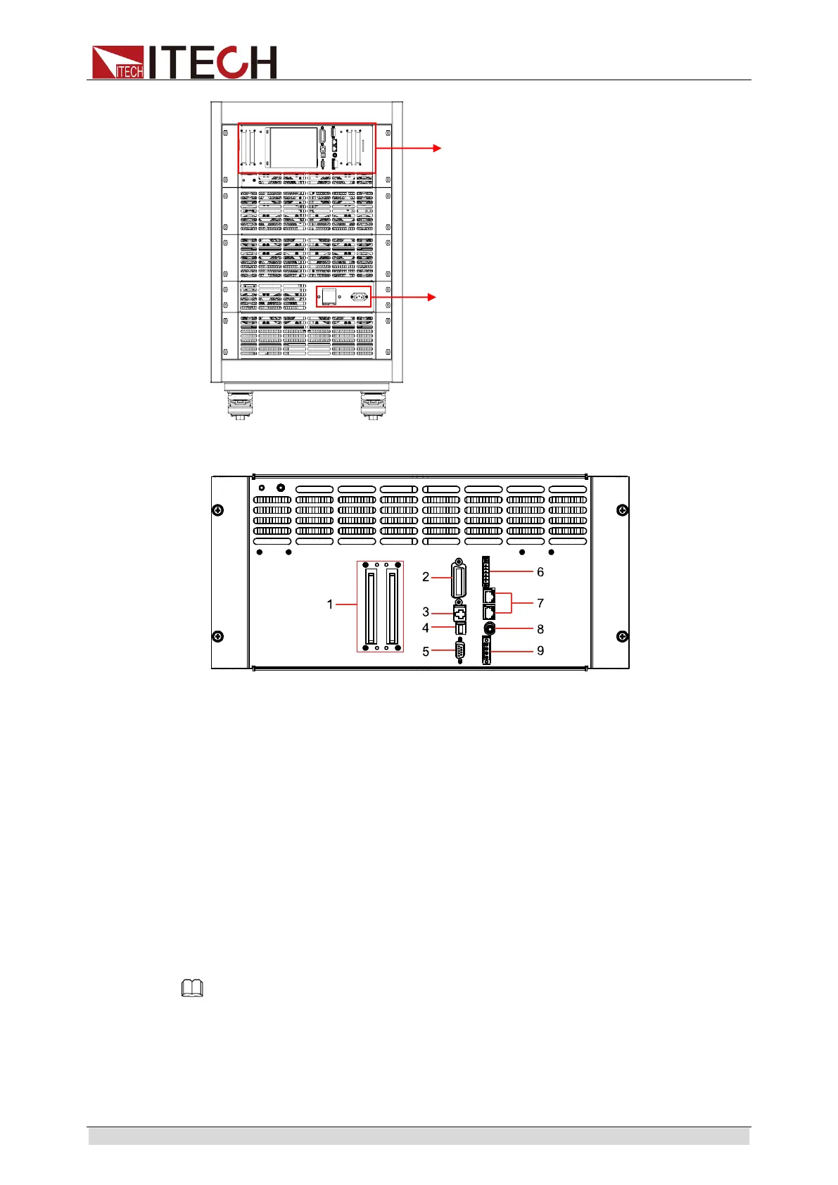
The detail of the red box in the figure above is as shown as follows:
1. Input terminal
2. GPIB interface
3. LAN interface
4. USB interface
5. RS232 interface
6. CAN interface( Optional ), external triggering terminal, external On/Off
control terminal and voltage fault indication terminal.
7. System bus
8. Current monitoring terminal
9. External analog 0-10 V control terminal and remote sense compensation
terminal
Note
2
7U and 37U rear panel terminals are exactly the same, please refer to the above
description, the following will not be repeated.
Rear panel terminal
AC power input terminal