Function and Features
Copyright © ITECH Electronic Co., Ltd. 38
automatically be OFF.
3. Press [Shift] + . (Trigger) key to start test. The board will display discharge
voltage, current discharge time and discharged capacity (AH).
4. Press [Esc] key to exit battery capacity test mode in any three methods.
3.13 CR-LED test function
With adding of diode break-over voltage setting in the IT8900 series electronic
load under conventional CR mode, the electronic load only works when voltage
applied at its both ends is higher than the diode break-over voltage to give a
real simulation of diode working principle, i.e., the ripple current at real LED test.
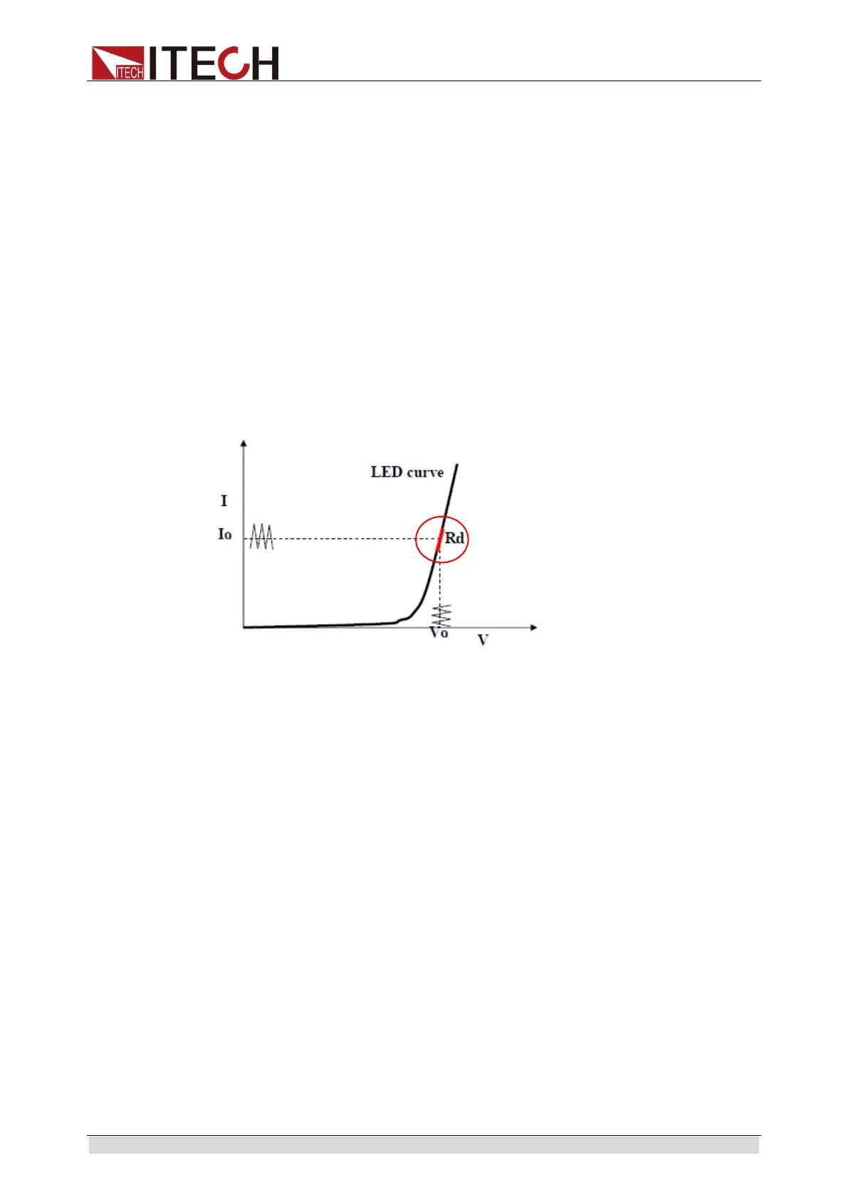
The I-V curve of LED is as shown below. Under conventional CR mode, the
electronic load only simulates the static working point of diode as shown in the
red circle of the following figure. It is unable to verify the dynamic characteristics
of LED under normal working conditions, and the status of accurate ripple
current.
Setting CR-LED Mode
Example: LED driver specification
The output current is 200mA and the range of output voltage is from 45V to 62V.
1. Start CR-LED function.
(1)
Press [Shift] + 9(Config) keys to enter configuration menu.
(2)
Press Right Key and select “CR-LED”. Press [Enter] key for entry. Select
“on” and press
[Enter] key.
(3) Press [Esc] key to exit.
2. Set CR mode and Vd value.
For example, the output voltage of LED driver is 50V, verify that whether
the output current of LED is rated current 200mA.
(1)
Press [CR] key and set corresponding constant resistance. (Set
CR=50Ω)
(2)
Press [Shift] + [CV] (Setup) keys for a series of related setting:
range=7500.0, high=130V, low=0V, which may remain the original values. Vd
will be set based on the calculation below. (Set Vd=40V)
(3)
Press the [Enter] key to save the settings.
3.
Press [On/Off] key to turn on load input.