2-76
CHASSIS MODIFICATIONS
D
AILY 4x4
Base - May 2007 Print 603.93.761
Electrical System: Modifications and Drawing-Off Power
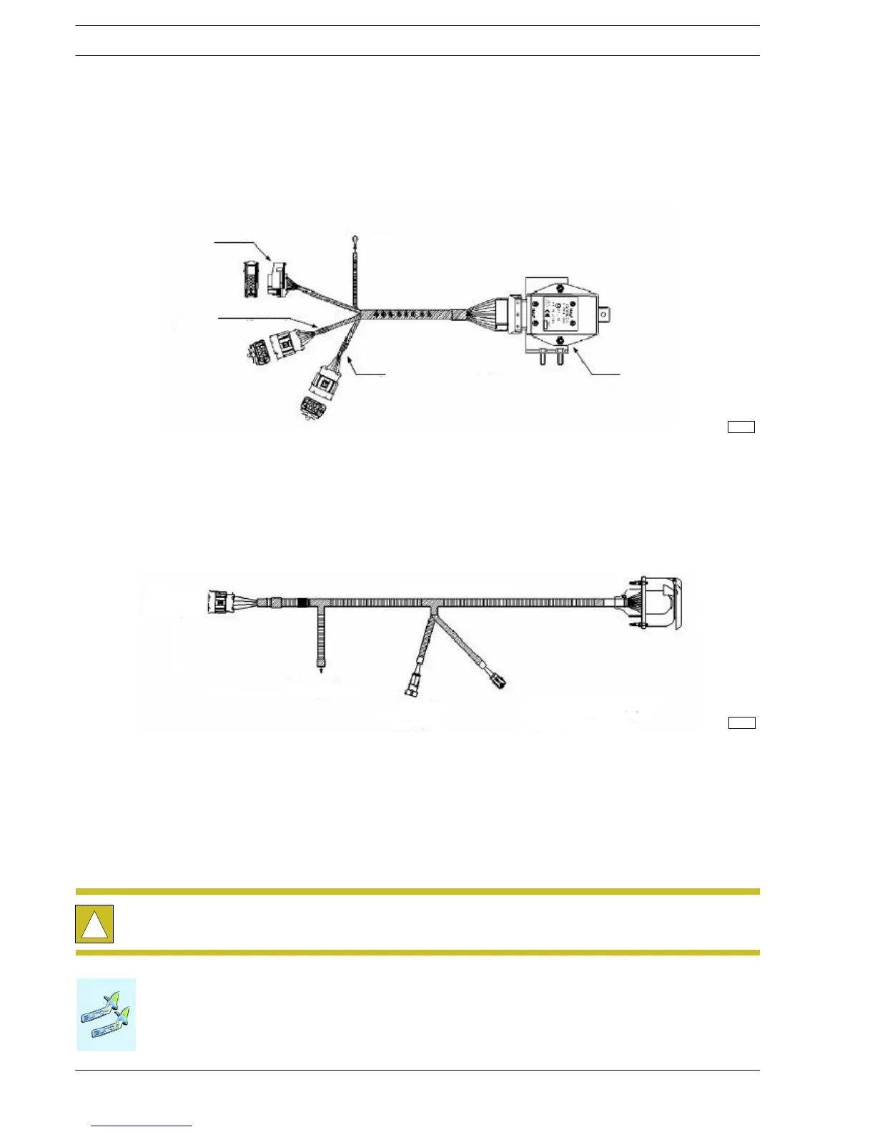
- Disconnect the grey connector between the chassis cable and the cab cable. Connect the interfacing bridle between the
electronic control unit and the connection s available on the vehicle, as illustrated in the diagram.
Figure 2.47
1. Electronic c o ntrol unit with bracket - 2. Red taping (con nect to th e added 13-pole chassis cable) - 3. Yellow taping
(connect to the c ab/bonnet cable) - 4. Connect to the chassis cable found on the vehicle - 5. Connect to the c hassis ground
114197
Figure 2.48
1. To be connected to the c hassis cable (from where the reversing gear sensor connection h ad come off) - 2. To be
connected to the reversing gear sensor - 3. Connect to the chassis ground - 4. To be connected to the control unit
connector - 5. Cable to be fitted onto the chassis
114198
For more details on connections and assembling, ask IVECO for the wiring diagrams.
!
Any damage to the lighting system caused by the failure to comply with the above procedure shall not
be covered by the warranty.

 Loading...
