CHASSIS MODIFICATIONS
2-77
DAILY 4x4
Print 603.93.761 Base - May 2007
Electrical System: Modifications and Drawing-Off Power
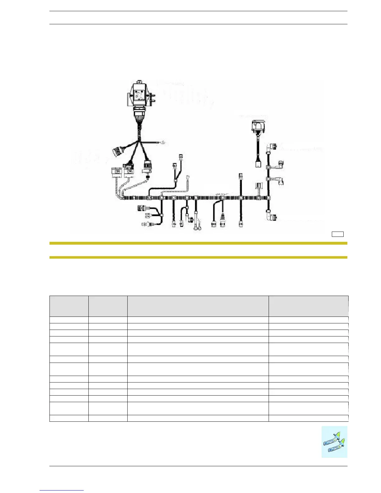
b) Factory-installed trailer conn ector (optional item 06520)
If the vehicle is ordered complete with the trailer conn ect or, th e full c ircuit will be delivered, which is made up of the electronic
control unit (already fitted into place), the set chassis c able and the 13-pole connector.
Figure 2.49
114194
Electronic control unit
13-pole connector
Rear lights
Rear lights
Chassis cable
Connections with the
cab cable
The diagram is shown for illustrative purposes only.NOTE
Description of 13-pin interface
Table 2.26
13-pole
connector
pin
Cable no. Description Remarks
1 1120 Rear left indicator bulb 1 bulb (21 W, 12 V)
2 2283 Rear fog light power supply 2bulbs(21W,12V)
3 0000 Ground -
4 1125 Rear righ t in dicator bulb 1 bulb (21 W, 12 V)
5 3335
Front left/rear righ t sidelights;
left licence plate light; left clearance ligh t
1bulb(5W,12V)
6 1175 Brake light power supply 2bulbs(21W,12V)
7 3334
Front right/rear left sidelights;
right licence plate light ; right clearance light
1bulb(5W,12V)
8 2268 Reversing light power s upply 1 bulb (21 W, 12 V)
9 7777 After fuse F23 on the CVM Battery positive
10 8879 After fuse F16 on the CVM Ignition-operated positive
11 0000 Ground -
12 6676 Trailer connection signal (ground)
Signal to be supplied if the parking
sensors are available
13 0000 Ground -

 Loading...
