CHASSIS MODIFICATIONS
2-59
DAILY 4x4
Print 603.93.761 Base - May 2007
Electrical System: Modifications and Drawing-Off Power
- Use existing holes for routing the cable. Take all the necessary precautions for protecting the body if additional h ole have t o
be drilled (use anti-rust paint, sheath, etc.).
- Ensure a good connection with the vehicle earth both at the base of the antenna and at the device fixing to ensure maximum
power transfer.
Radio transmitters are typically fitted on the dashboard in the gear lever area or in the header rail above the driver (see Figure 2.33).
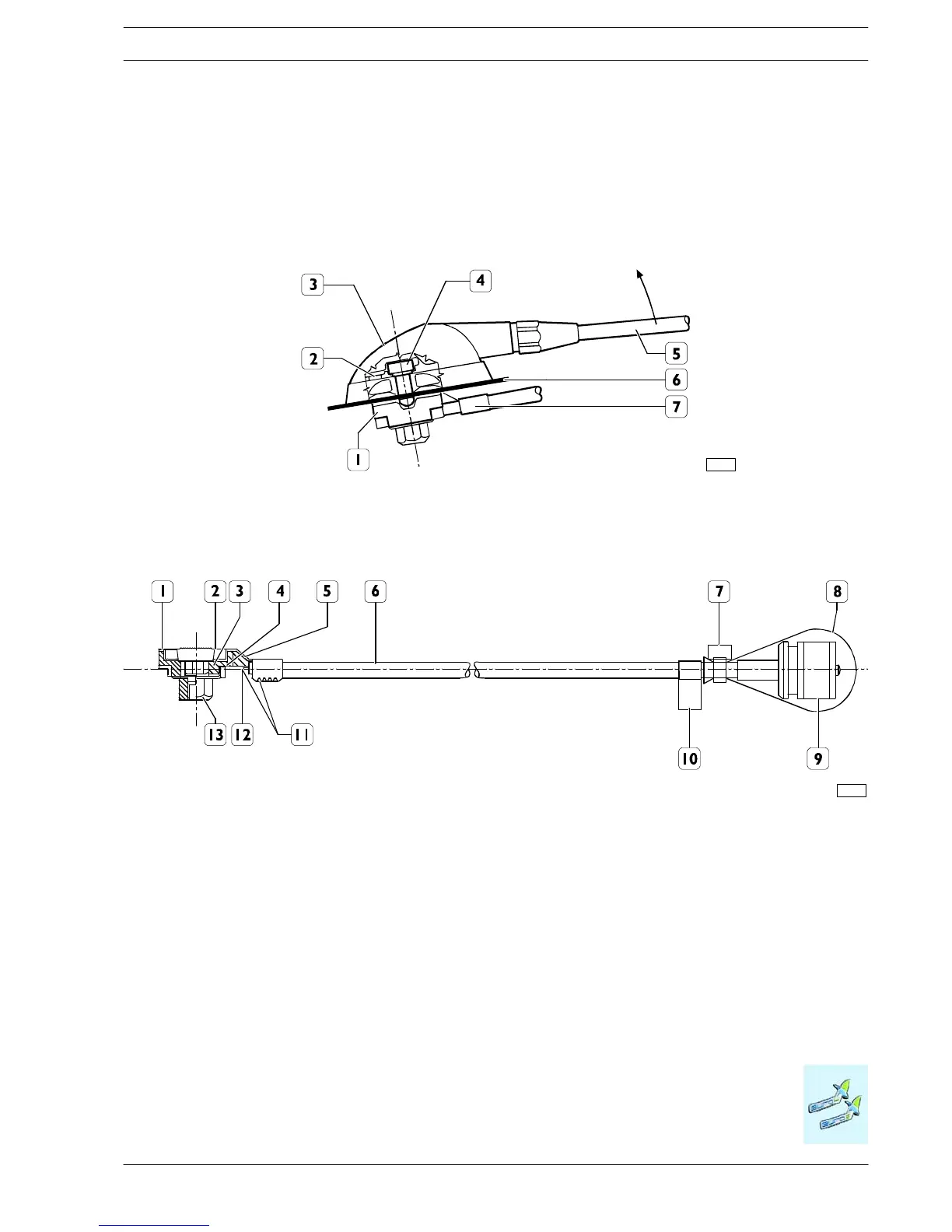
Figure 2.31
1. Ant enna support - 2. Gasket (P/N for spares 244614) - 3. Fixed joint cover (P/N for spares 217522) - 4. Fixing screw
M6x8.5 (torque to 2 Nm) - 5. Antenna (spare P/N for c omplete rod 675120) - 6. Roof - 7. Antenna extension lead
98915
Figure 2.32
1. Antenna con nector - 2. Groun d wire - 3. Insulator - 4. S ignal wire - 5. Capacitor (100pF) - 6. Cable RG 58 (cha racteristic
impedance = 50 Ω) - 7. Clamp - 8. Protective cap - 9. Connector (N.C. SO - 239) transceiver side - 10. Test executed sticker
- 11. The 100pF capacitor must be soldered on the lower pin and crimped to the ground braid - 12. The lower pin must be
soldered to the core c onductor of the cable - 13. Nut
99349

 Loading...
