17
2.2.2.6 SECTION CONTROL BY AUTHORIZATION
The service technician can configure the control panel to be controlled just by authorization. This way the status
of all sections can change by authorization on a keypad (by typing an access code or using an RFID chip).
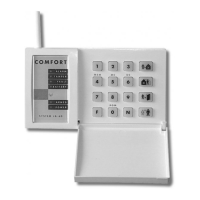
2.2.2.7 SECTION CONTROL FROM THE KEYPAD’S MENU
Control from the keypad menu:
o Authorize yourself using a valid code or an RFID chip
o Enter the menu by pressing ENTER
o Section Control → ENTER
o Select the desired section using arrows
o Pressing ENTER repeatedly will change between section statuses
(partially set / set / unset)
Partial setting:
Fully set:
o Press ESC to exit the menu.
1
1
2.3 OPERATING THE SYSTEM WITH A KEYFOB
Keyfobs must be enrolled into the system by the installer. The keyfob can be linked
to specific users, which will prevent SMS text message notification to the user who
is interacting with the system at the moment (if notification parameters are set
up in this way). The keyfob can provide either bi-directional communication,
confirming the execution of a command with a coloured indicator light,
or one-way without any confirmation. Keyfobs control and indicate battery
status and are equipped with optical and acoustic indication.
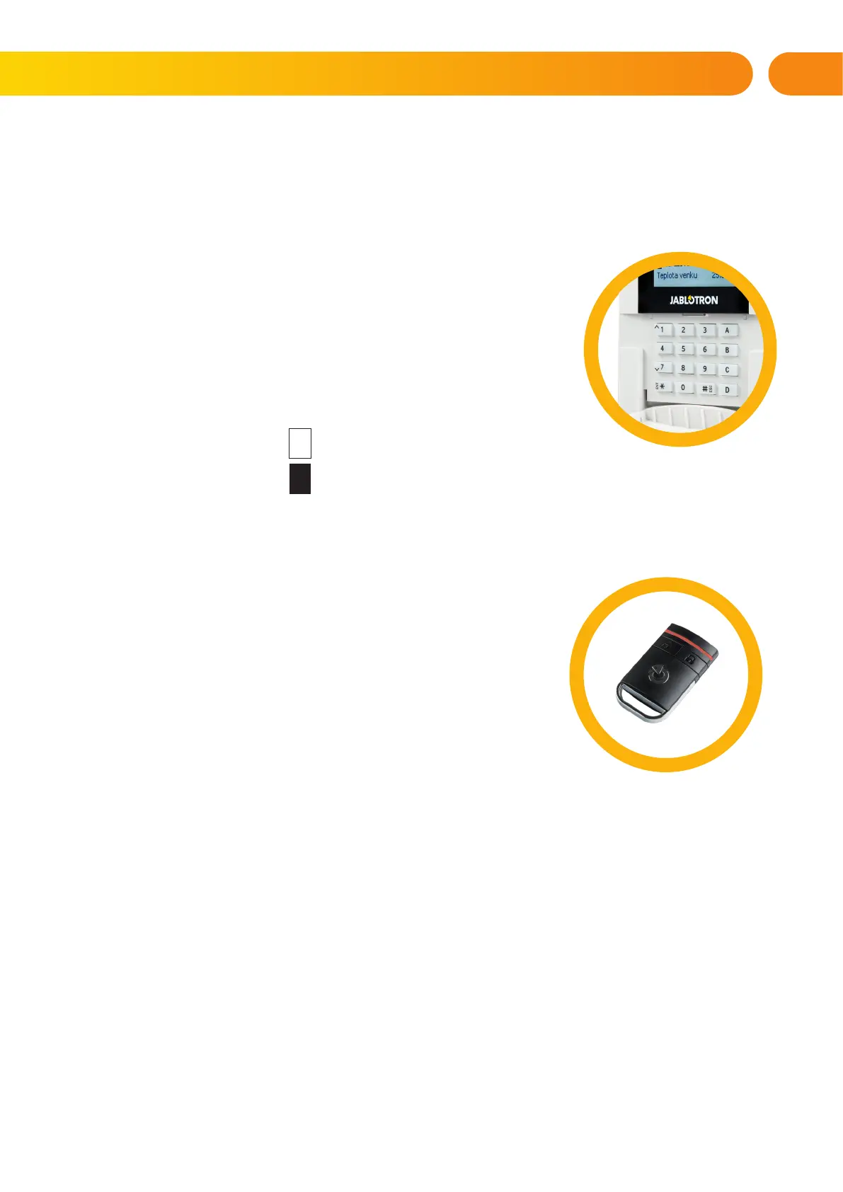
Bi-directional keyfob
The button functions are differentiated by lock icons. The closed lock icon sets
programmed sections; the opened lock icon unsets them. Correct command execution
is confirmed by an LED light; unsetting – green, setting – red. A communication fault (out
of the control panel’s range) is indicated by a yellow LED light flashing once. The buttons with symbols of full and
empty circles can control another section. Buttons of the keyfob can also be configured to control PG outputs in
different modes: the first button switches on/ the second switches off, each button can have an individual function
when impulse or change functions are used. For more functions, it is possible to press two buttons at the same time.
This way a 4-button keyfob can have up to 6 individual functions or one PG status output (e.g. turn the lights on and
off), alternatively two PG outputs (e.g. a garage door and door lock).
If the system is configured to Set after confirmation (chapter 2.2.1.1) the detector will indicate unsuccessful
setting with a green LED light if a device is triggered. It is necessary to confirm setting by pressing
the lock button again. A set section will be confirmed by a red LED light.
The keyfob buttons can be blocked to prevent accidental pressing. A command will be sent out when
a button is pressed repeatedly.
A low battery is indicated acoustically (with 3 beeps) and optically with a yellow flashing LED after
pressing a button.
For more information, consult configuration of the remote control with your service technician.
2. OPERATING THE JABLOTRON 100 SYSTEM