Page 12
Section 3. Installation Instructions
3.1 Materials and Tools
NOTE Salt not included. See Section 4, Pool Water Preparation.
Installation Materials Furnished
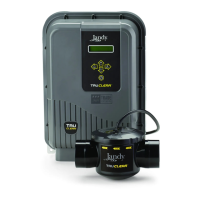
PureLink
TM
with Power Center
(1 ea.) AquaLink
®
RS PureLink power center (Standard or Breaker)
(2 ea.) Wire Nuts
(1 ea.) Installation Template
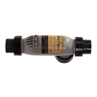
PLC700 / PLC1400 Cell Kits
(1 ea.) Electrolytic Cell with 2”-2½” Universal Unions
(1 ea.) Sensor with 16 ft (4.88m) Cable and O-ring
(1 ea.) Universal Union Nut
(1 ea.) 16 ft (4.88 m) DC Power Cord
(1 ea.) Strain Relief
(1 ea.) Owner’s Manual - Warranty Information
AquaPure Control Center
(1 ea.) AquaPure Control Center
(2 ea.) Wire Nuts
(1 ea.) Installation Template
Tools Needed for Installation
Tape Measure
Phillips & Flathead Screwdrivers
Pliers
Hacksaw
Voltmeter to determine line voltage of AC wiring to power supply
Electric Drill Motor and 1/4 “ masonry drill bit for mounting power
supply on block or stucco wall
An NSF
®
*approved All Purpose Cleaner Primer
An NSF approved All Purpose Cement (such as Weld-On 794, 793)
* NSF is a registered trademark of the NSF International.
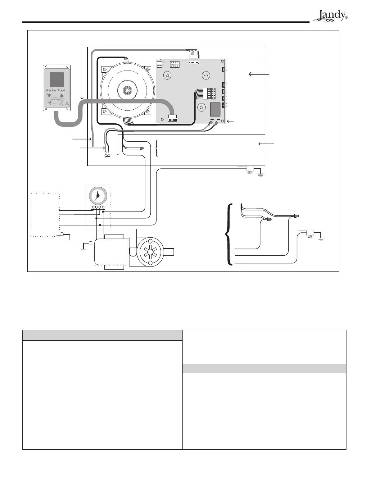
Power Center Wiring Diagram
CHLORINE GENERATOR
POWER INTERFACE
J13
J12
J11
BLK/YEL
BLK/RED
BLK/WHT
BLACK
Factory wired for 240 VAC service; Middle primary
wires connected together. If electrical service is
120VAC, the power supply must be modified.
Flow, Salinity, Temp Sensors
RIBBON CABLE TO
USER INTERFACE
GR
Y
BK
R
LOW VOLTAGE RACEWAY
HIGH VOLTAGE
HEAT SINK
L - BRACKET
CHLORINE GENERATOR
USER INTERFACE
To Chlorine Generator Cell
View of chlorine generator PCB
shown with transformers and
components located behind front
face plate.
PRIMARY
SECONDARY
CHLORINE GENERATOR
TRANSFORMER
BLK/WHT
BLK/YEL
BLK/RED
BLK
Use Copper Conductors Only – Rated for 90°C Minimum
Re-wired for
120 VAC
Load 2
Load 1
Load 1 (Hot)
Ground (Chassis)
Ground (Chassis)
To Earth
Bonding Point
To Earth
Bonding Point
Load 2 (Neutral)
240
VAC
Pool Pump Timer
Circuit Breaker
Panel
Line 1
Line 2
Ground
50/60 Hz
3 wire
3
12
6
9
Filter Pump
(240 VAC)
Figure 2c. Wiring Diagram for the AquaPure® System