Page 25
3.8.2 Connection of PureLink
TM
Chlorine Generator Electronics to an AquaLink
®
RS
Control System
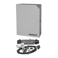
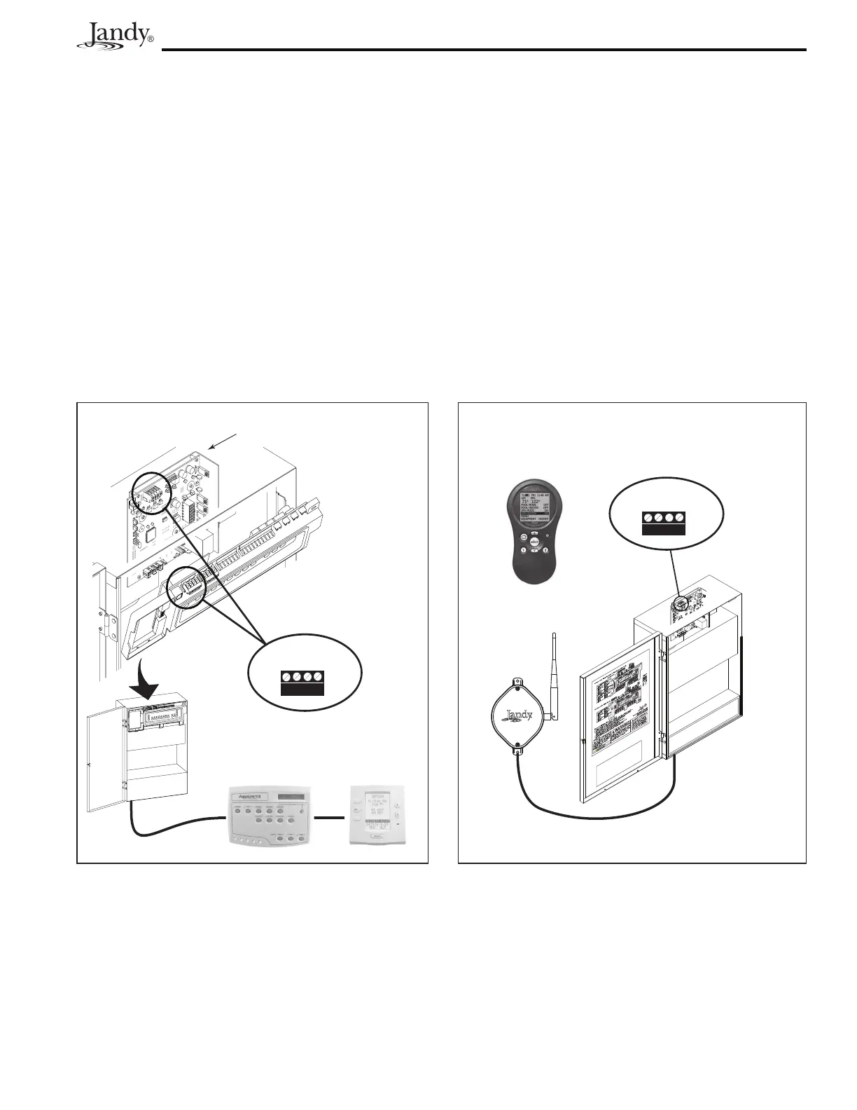
The chlorine generator electronics in the PureLink Power Center and the AquaLink
RS controller require a
four (4) wire connection to communicate. Any outdoor rated four (4) conductor cable, minimum 22 AWG,
can be used. Locate the appropriate screw terminals on the circuit board according to Figures 16a and 16b.
Wire the chlorine generator power interface board
from the red 4-pin terminal bar to the AquaLink
RS red
4-pin terminal bar (see Figure 16a).
ReferringtoFigures2aor2b,wirethePureLinkpowercentertransformertotheloadsideofthelterpump
relay.
Figure 16a. Wiring a PureLink
TM
Control System
Network
or
All Button
OneTouch
PureLink
Power Center
Chlorine Generator
Power Interface Board
4 3 2 1
RED
BLK
YEL
GRN
Red, 4-Pin
Terminal Bar
TM
Figure 16b. Wiring a PDA
Control System Network
Transceiver
J-box for PDA
PDA
PureLink
Power Center
4 3 2 1
RED
BLK
YEL
GRN
Red, 4-Pin
Terminal Bar