Page 24
3.8 Connection of Chlorine Generator Electronics to an AquaLink
®
RS Control System
TheJandyAquaLinkRSisamulti-functionpoolcontrollerthatcanfullycontrolthefunctionofthechlorine
generator.Thechlorinegeneratoruserinterfacewilldisplay“JA”whenanyofitsbuttonsarepressedwhile
the AquaLink
RS is in control. Adjustment of the chlorine production rate or Boost mode can be controlled
from the main menu of the AquaLink RS controller (All Button, OneTouch™, or PDA). Boost mode can
also be activated from the chlorine generator user interface while the AquaLink RS is online. Refer to the
AquaLink RS Operation Manual (or AquaLink RS PDA Operation Manual) for more information. The
chlorine generator’s user interface will display temperature, salinity, service codes, and LED indicators as
normal.
NOTE The AquaPure
®
and PureLink
TM
chlorine generator electronics will communicate with AquaLink
®
RS using
rmwareversionsJJorlater.
3.8.1 Wiring AquaPure Control Center to an AquaLink
RS Power Center
In the AquaLink
RS power center enclosure, wire the AquaPure
Control Center input power directly to the
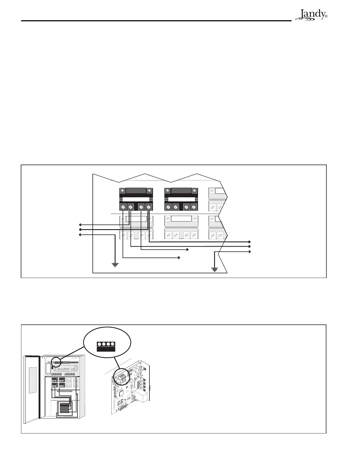
LOADSIDEofthelterpumprelay(seeFigure14).
Filter Pump Relay
Aux. 3 Relay
Load 2
Line 2
Load 1
Line 1
To AquaPure
(240 VAC)
To Breaker
Panel
To Filter Pump
240 VAC
AquaLink RS Power Center
Figure 14. Power Connection between AquaPure Control Center and AquaLink
®
RS Power Center
TheJandyAquaLink
RS and AquaPure
use a four (4) wire connection to communicate and can be wired up
to500feetapart.Anyoutdoorratedfour(4)conductorcable,minimum22AWG,canbeused.Locatethe
appropriatescrewterminalsonthecircuitboardaccordingtoFigure15.WiretheAquaPure
®
from the red
4-pin terminal bar to the AquaLink
RSred4-pinterminalbar(seeFigure15).
OPTIONAL
4 3 2 1
RED
BLK
YEL
GRN
Red, 4-Pin
Terminal Bar
Chlorine Generator
Power Interface
Board
AquaLink RS Power Center
NOTE The screw terminals are removable to aid in
installation.
IMPORTANT Attach the wires to the like-numbered screw
terminals on both the AquaPure and AquaLink RS.
Figure 15. Communication Connection between AquaPure
®
Control Center and AquaLink
®
RS Control
System