Page 17
3.5 Model Conguration
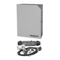
Thechlorinegeneratorpowerinterfaceboardisconguredasa1400modelbyfactorydefault.However,
thepowerinterfaceboardcanbeconguredasa700model.
Toconguretheboardasa700model,usecuttingplierstocuttheJL1jumperasshowninFigure9.
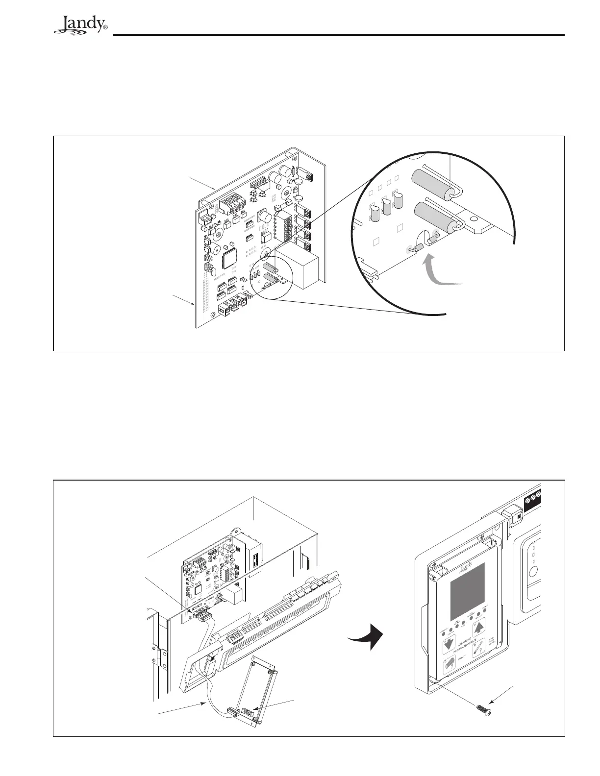
Figure 10. Installation of the User Interface
3.6 Installation of the Chlorine Generator User Interface on an AquaLink
®
RS or PDA Bezel
1. Onthechlorinegeneratoruserinterfaceboard,connectoneendoftheribboncabletothe16-pinJ1
connector as shown in Figure 10.
2. Connecttheotherendoftheribboncabletothepowerinterface16-pinJ1connector.
3. Attach the chlorine generator user interface board to the bezel using the four (4) screws provided.
Figure 9. Chlorine Generator Power Interface Board
J1 Connector,
Chlorine Generator
Power Interface
Board
Heat Sink
L-Bracket
Bezel Assembly
AquaLink RS Daughter Card
Mounting Area
Self-Tapping
Screw (2)
Screws (4)
Ribbon Cable
J1 Connector,
User Interface
4 3 2 1
Cut JL1 Jumper to
configure board as
Model AP700
Chlorine Generator Power
Interface Board
Heat Sink
L-Bracket