Page 22
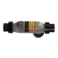
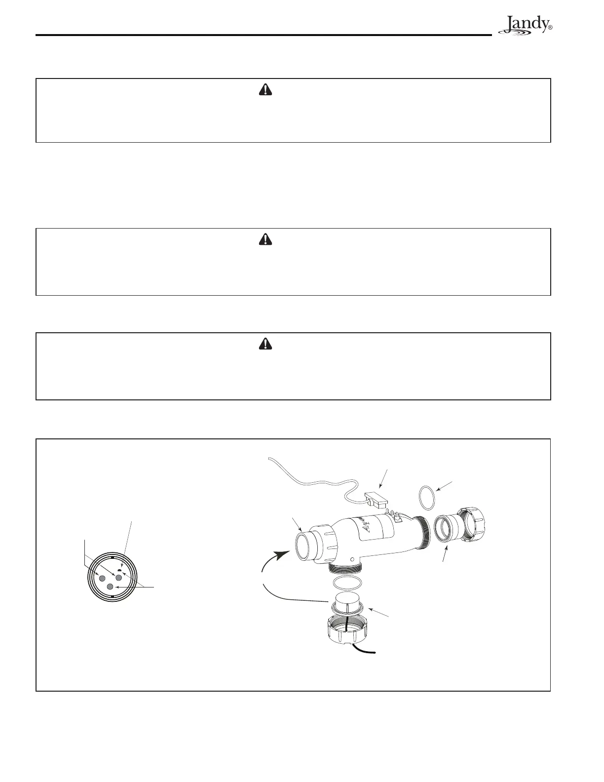
Figure 11. Cell Installation and Flow/Temp/Salinity Sensor
* Ensure the DC Plug is properly and securely
connected to the terminal studs of the cell.
DC Cord Plug is Connected
to Terminal Studs*
O-Ring
Seal
Flow/Temp/Salinity Sensor
O-ring and Union Nut
2 x 2½” or 50mm Tailpiece
with Coupling Nut
2” x 2½” or
50mm Union
or
Sometimes
Not Covered
Temperature
Sensors
Flow/Temp/Salinity Sensor Face must
be clean at all times for proper operation
Salinity
Studs
5. ConnecttheDCcordtothecontrolcenter.FeedtheDCcordthroughthesamestrainreliefttingasthe
ow/temp/salinitysensor.PlugtheDCcordasshowninFigure2a,2b,and2c.
CAUTION
Do not bury the electrolytic cell DC cord or Sensor cable directly in the ground. Direct burial can cause
damage to an electrical cord/cable.
6. Tightenstrainreliefttingscrewsfortheow/temp/salinitysensorcableandtheDCcord.Donotpull
ow/temp/salinitysensorcableorDCCordtootight.Allowalittlecableslackinsideofcontrolcenter
enclosure.
7. Checkthewiringpriortoreattachingfrontcover.Besuretheow/temp/salinitysensorispluggedin.
The DC cord should be plugged in. Also, check the AC wiring.
CAUTION
Donotovertightenthestrainrelieftting.Overtighteningcancausedamagetotheow/temp/salinity
sensor cable.
8. Ifdisconnected,plugtheribboncableintotheJ1connectorstheuserinterfaceandthePowerInterface
PCB (See Figures 2a, 2b, 2c, and 10).
CAUTION
Donotoperatetheelectrolyticcellwithoutwatercirculation.Abuildupofammablegasescanresultin
FIRE or EXPLOSION.