Issue #4119-IGE-01-00 © 2020, JAPAN CASH MACHINE CO., LTD.
Standard Interface Circuit Schematics RBA-40C™ Banknote Acceptor Section 6
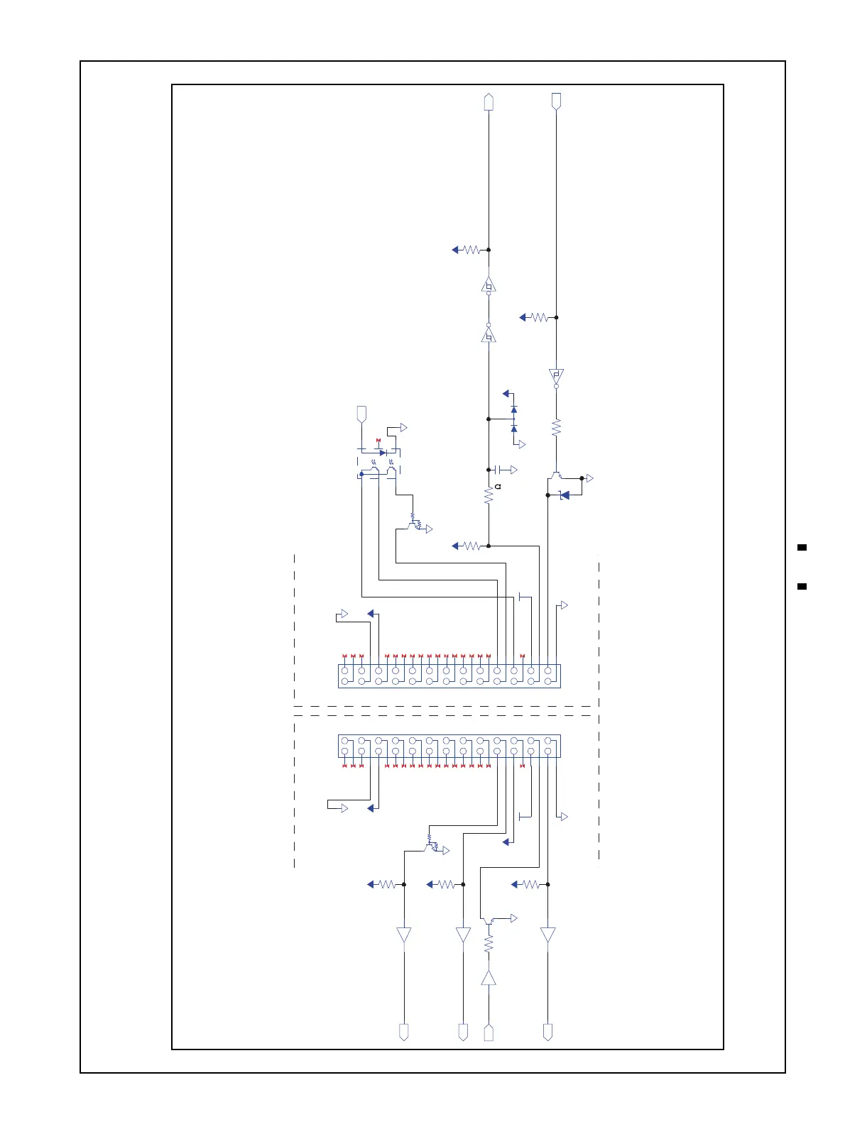
6 STANDARD INTERFACE CIRCUIT SCHEMATICS
This section provides the interface circuit schematics of the RBA-40C™ Series Banknote Acceptor (RBA-40C).
RBA-40C TTL and Encoder Interface Circuit Schematic
Figure 10 RBA-40C TTL and Encoder Interface Circuit Schematic
Figure 10 RBA-40C TTL and Encoder Interface Circuit Schematic
1
2
3
4
5
6
7
8
9
10
11
12
13
14
15
16
17
18
19
20
21
22
23
24
25
26
1
2
3
4
5
6
7
8
9
10
11
12
13
14
15
16
17
18
19
20
21
22
23
24
25
26
NC
NC
NC
PWGND
+5V
NC
NC
NC
NC
NC
NC
NC
NC
NC
NC
NC
NC
NC
MD-100_ENC1
MD-100_ENC2
MD-100_5V
NC
+24V
TTL RxD
TTL TxD
PWGND
NC
NC
NC
PWGND
+5V
NC
NC
NC
NC
NC
NC
NC
NC
NC
NC
NC
NC
NC
MD-100_ENC1
MD-100_ENC2
MD-100_5V
NC
+24V
TTL RxD
TTL TxD
PWGND
8
3
6
4
2
1
5
4.7k
+5V
9
3
4
GND
5
4.7k
4.7k
+5V
+5V
+5V
GND
GNDGND
+24V
+5V
GND
+5V
GND
+24V
6
1
GND
2
4.7k
D5V
UMH10N
KIT3032S GND
6
5
4
1
2
3
EDZCV6.8B
EMX52
100p
GND
GND
21
3
D5V
GND
3
4
5
DRA-26SC-JC DRA-26PC-JC
DAN217WM
2.7k 5 3
6217
WH14 WH14
+3.3V
15k
+3.3V
15k
WH14
100
Host Machine Side Example RBA-40C Unit Side