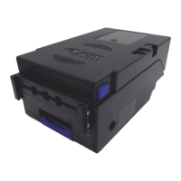
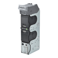
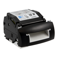
Section 8 RBA-40C™ Banknote Acceptor Troubleshooting
Issue #4119-IGE-01-00 © 2020, JAPAN CASH MACHINE CO., LTD.
Error Codes
Table 17 lists the various LED Flash Error Code causes and solutions.
Table 16 Communication Fault Conditions
Symptoms/Error
Messages
Possible Fault Causes Corrective Action Required
Cannot
communicate with the
Host Machine
DIP Switch settings are
incorrect.
Set all DIP Switches to OFF.
Connectors are off or loosely
connected.
Firmly reseat all of the Communication Connectors.
Damaged Connector Pins
Check for any bent, missing or damaged Pins in the Connector Plugs and
mating Receptacles.
CPU Board is corrupted.
Exchange the CPU Circuit Board with a known good Circuit Board. Refer to
Section 4 "Disassembly/Reassembly" on page 4-1 of the upcoming RBA-40C
Operation and Maintenance Manual regarding Circuit Board Removal.
Incorrect Interface
Verify that the correct interface between the Host Machine and the Banknote
Acceptor is being used.
Table 17 RBA-40C Unit LED Flash Error Codes
Red LED Green LED Error Solutions Relative Parts/Sensors
Red
(1)
Green Lit
Boot ROM Error
The Boot Program that is
supposed to run after Power is
supplied is not correctly written
in ROM, or it cannot be read
• Check that the relative part(s) is properly
assembled and/or Harness connected.
• CPU Circuit Board
Red
(2)
Green Lit
External Flash ROM, Boot I/F
Area, I/F Area and/or Country
Area Error
The Boot Interface, Interface
and/or Country Area was not
written correctly or cannot be
read
• Re-download the Program.
• Check that the relative part(s) is properly
assembled and/or Harness connected.
• CPU Circuit Board
External Flash ROM Write
Error
The Main Operating Program is
not written into the ROM
correctly
• Re-download the Program.
• Check that the relative part(s) is properly
assembled and/or Harness connected.
• CPU Circuit Board
Red
(3)
Green Lit
CPU Internal RAM Check Error
RAM reading or writing was not
properly performed
• Check that the relative part(s) is properly
assembled and/or Harness connected.
• CPU Circuit Board
Red
(4)
Green Lit
External RAM Error
External RAM reading or writing
was not properly performed
• Check that the relative part(s) is properly
assembled and/or Harness connected.
• CPU Circuit Board
Red
(5)
Green Lit
FRAM Error
FRAM saving was not properly
performed
• Check that the relative part(s) is properly
assembled and/or Harness connected.
• CPU Circuit Board
Red
(6)
Green Lit
Downloading File Error
Downloading files does not
proceed
• Select a file supported by the RBA-40C
Unit.
• A file to download
Red
(7)
Green Lit
Magnetic Sensor Setting
Abnormal
An abnormal Magnetic Sensor
setting is detected
• Check that the relative part(s) is properly
assembled and/or Harness connected.
• Clean or calibrate the relative Sensor(s).
• Magnetic Sensor
Red
(8)
Green Lit
I2C Access Error
While I2C communicating,
Sensors detect an abnormal
operating condition.
• Check that the relative part(s) is properly
assembled and/or Harness connected.
• Magnetic Sensor
• CPU Circuit Board
Red
(9)
Green Lit
SPI Access Error
While SPI communicating,
Sensors detect an abnormal
operating condition.
• Check that the relative part(s) is properly
assembled and/or Harness connected.
• CPU Circuit Board
Red
(10)
Green Lit
FPGASPI Access Error
While FPGA SPI
communicating, Sensors detect
an abnormal operating condition.
• Check that the relative part(s) is properly
assembled and/or Harness connected.
• CPU Circuit Board
NOTE: If the error is not resolved, change the relative part(s).