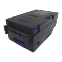
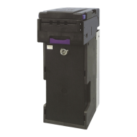
RBA-40C™
Banknote Acceptor
Table of Contents
Issue #4119-IGE-01-00 © 2020, JAPAN CASH MACHINE CO., LTD.
Page
1 GENERAL INFORMATION ........................................................................................1
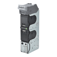
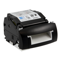
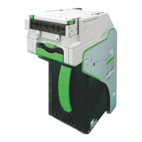
RBA-40C Unit......................................................................................................................1
Product Descriptions.........................................................................................................2
Model Descriptions...............................................................................................................2
Type Descriptions ................................................................................................................2
Software Descriptions ..........................................................................................................2
Precautions.........................................................................................................................2
User Cautions ......................................................................................................................2
Installation Cautions........................................................................................................................ 2
Mounting, Dismounting & Transportation........................................................................................ 3
Operation Cautions ......................................................................................................................... 3
Preventive Maintenance.......................................................................................................3
Banknote Fitness Requirements..........................................................................................3
Primary Features................................................................................................................4
Component Names ............................................................................................................5
2 SPECIFICATIONS ......................................................................................................6
Technical Specifications ..................................................................................................6
Environmental Specifications ..........................................................................................7
Electrical Specifications....................................................................................................7
Structural Specifications...................................................................................................7
3 INSTALLATION ..........................................................................................................8
DIP Switch Settings ...........................................................................................................8
SW1 (DIP Switch Block 1)....................................................................................................8
SW2 (DIP Switch Block 2)....................................................................................................8
4 CONNECTOR PIN ASSIGNMENT .............................................................................9
Power Supply Connector Pin Assignment; TTL and Encoder ............................................9
Power Supply Connector Pin Assignment; USB and Encoder .........................................10
Bezel Connector Pin Assignment ..................................................................................11
5 PREVENTIVE MAINTENANCE ................................................................................12
Clearing a Banknote Jam...................................................................................................12
Opening the Centering Mechanism....................................................................................12
Cleaning Procedures..........................................................................................................12
RBA-40C Sensors and Cleaning Locations .......................................................................13
6 STANDARD INTERFACE CIRCUIT SCHEMATICS ................................................15
RBA-40C TTL and Encoder Interface Circuit Schematic ...................................................15
RBA-40C USB and Encoder Interface Circuit Schematic ..................................................16
RBA-40C Bezel LED Light Controller Circuit Schematic....................................................17
7 OPERATIONAL FLOWCHARTS..............................................................................19
Initialization and Banknote Acceptance Flowchart.............................................................19
Validation Flowchart...........................................................................................................20
Discharging Flowchart........................................................................................................21