27
TO REPLACE THE TRANSDUCERS:
Ø Disconnect the power from the rear of the machine.
Ø Remove the weight tray.
Ø Remove the protection underneath the vibratory assembly.
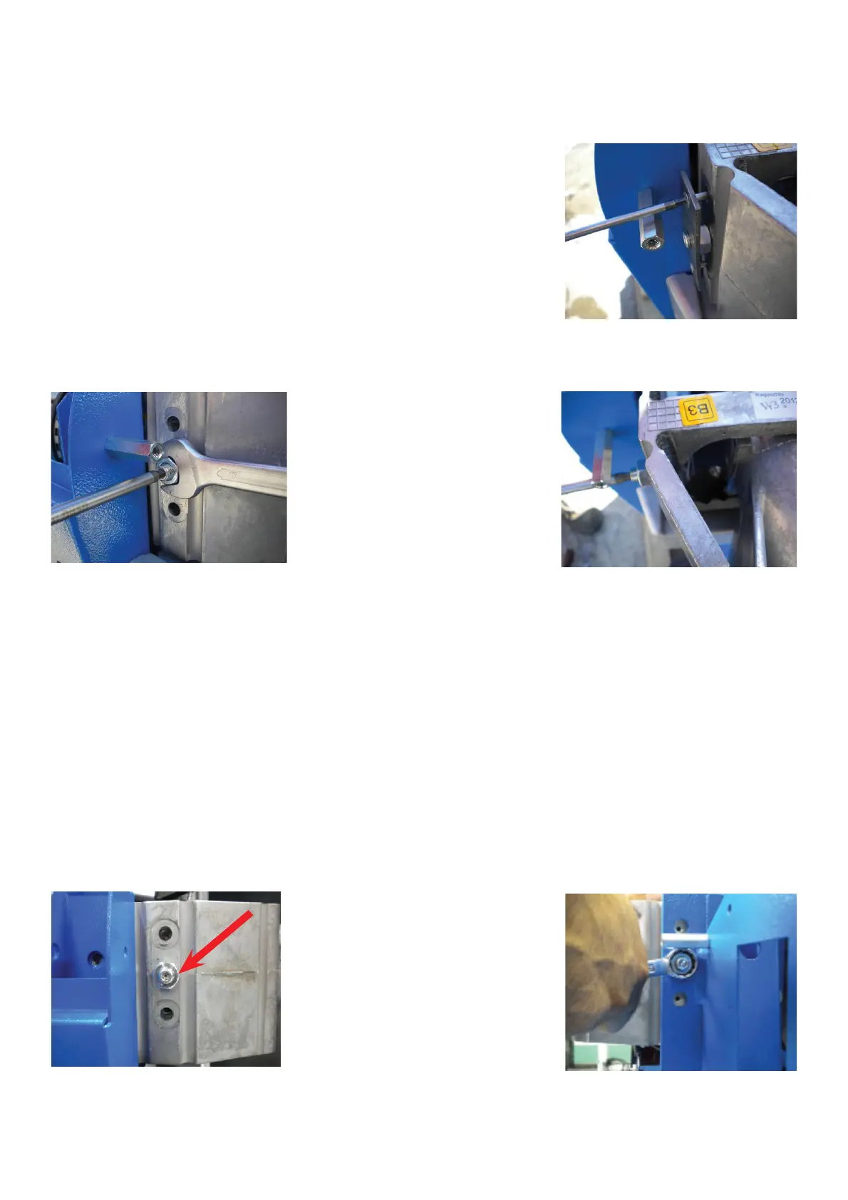
Ø Using a 2.5mm hex key remove the preloading plate.
Ø Using a 17mm wrench loosen the jam nut.
Ø Using a 5mm hex key, back the set screw o! by turning counter/clockwise. Do not lose the ball bearings on each
end of the tranducers. These allow the transducer to center easily on the vibratory member.
Ø If the transducer is being replaced , the lead “+” is already signed on the wire with a black band. Cut the two wires
at the transducer.
Ø The transducer attached to wires 11 and 12 of connector X6 is placed in the front; that one attached to wires 15
and 16 is placed in the rear of the vibratory assembly.
To " t and mechanically pre-load a transducer, carry out the following steps:
Ø Insert the wires into the transducers: the cables with black band must be " tted on the positive lead.
Ø The two setscrews M10x1x29 with ball sockets (inverse cones) should be screwed into the vibratory plate of 20-
mm / /0.79inch thickness and the rigid support plate welded to the cabinet.
Ø Put some sti! grease in the recesses at both ends of the transducer.
Put 8-mm Ø ball bearing in the recesses.
Ø Insert the transducer in the slot of the vibratory plate with one of the balls contacting the indentation opposite the
setscrew. Tighten the setscrew until the transducer is centered.
Ø Route the transducers with leads downward to avoid any possible condensation concentration inside of the leads
them selves.
Ø Screw on the locknut M10x1 (17-mm across the fl ats), but do not tie up yet.
Ø Tighten the M10x1setscrews at 0.4Nm / 0.3lbsft shown by red arrow.
Ø Fasten the locknut. To prevent the setscrew to turn, hold it with the hexagon wrench 5-mm inserted.