79
C83 Calibration of the unbalance measurement with wheel/test rotor.
Options: None
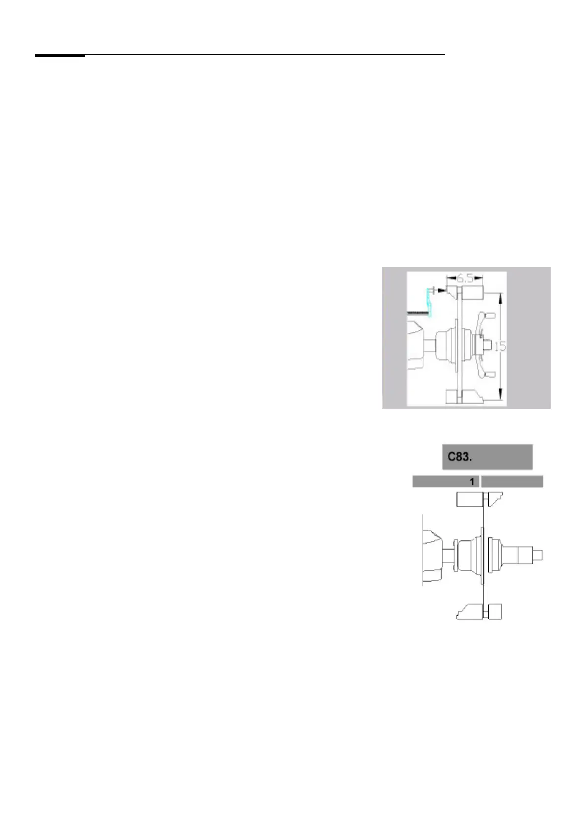
Special function: In case of using of a wheel, use a 6.5”x15” steel rim with a maximum unbalance of 10g in each
side.
Description: With the calibration of the unbalance measurement the following are determined:
- the sensitivity of the transducers,
- the phase di! erence of the transducer signals,
- the comparative data for readjustment by the operator and temperature compensation
- the phase shift of the unbalance signal ampli" ers and
- the angular deviation
After the 1
st
step, that is the measuring run, a beep signal is heard.
After acknowledgement/setting of weight size in step 2 a beep signal is heard (in addition to the beep made by the
key).
In step 6 the ambient transducer temperature will be read out for 1 second.
Mount the calibration tool or the wheel on the balancer shaft: Set the calibration tool or wheel data.
Step 1: Lower the wheel guard to begin the measuring run.
Step 2: If a Pruefrotor is used, screw the 100g / 3.5Oz weight on the left side of the Pruefrotor. If a wheel is used
attach the 100g / 3.5Oz weight to left rim edge. If the the weight is not “100”, press and hold the “ENTER VALUE” key
and rotate the shaft until the custom weight is displayed.
ROTATE THE CALIBRATION TOOL / WHEEL WITH 100GR AT 12 O’CLOCK.
Press the “RETUN” key to enter the value of the test weight.