83
C88 Calibration of 12 o’clock position for • tting position of weights
Options: None
Special function: None
Description: With this calibration code it is possible to compensate for the individual angular deviation of a
machine. During the basic calibration in the factory this code will only be carried out if there is a clearly noticeable
angular deviation, and not as a general procedure. Since the angle of the static unbalance is used for this purpose,
the service technician can select the correction plane in which he can best and most accurately assess the vertical
position above the main shaft.
One possibility is to attach the weight to the left-hand correction plane and to use the gauge arm as reference point,
in which case it is fi rst necessary to make sure that the gauge arm is aligned parallel to and vertically above the main
shaft.
The second possibility is to attach the weight in the right-hand rim " ange and to turn the weight in step 3 so that it is
exactly vertical below the main shaft. In this position a plumb line can be used as the reference point.
Possible angle correction is read out in +/- 5 degrees (used to be called increments)
If the angular deviation is more than +/- 5 degrees the reading will be “---”.
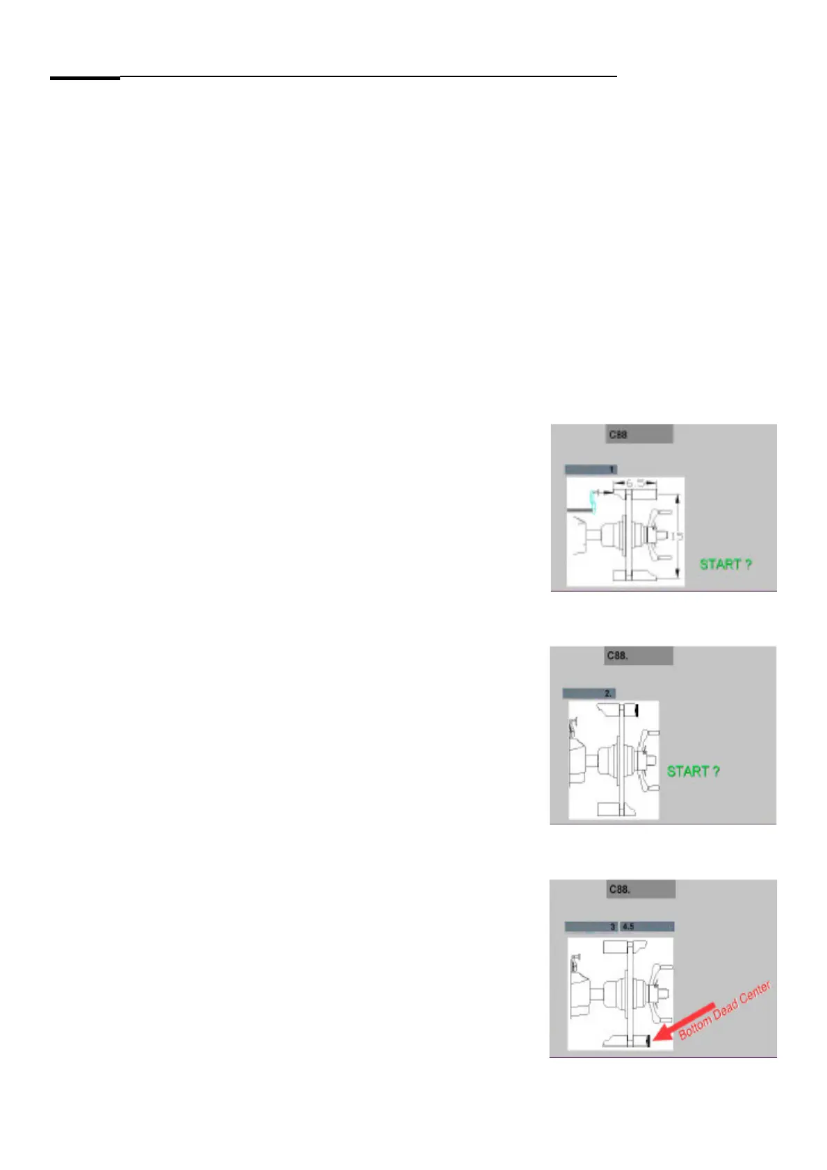
Mount the Pruefrotor on the balancer shaft and enter in the parameters of the Pruefrotor using the balance display.
Step 1: Low the wheel guard to begin the measurement run.
Step 2: Attach the 100 gram weight to outside of the Pruefrotor and low
the wheel guard.
Move the shaft to locate the 100 gram weight at “BOTTOM DEAD CENTER”
position.Use a spirit level or electronic inclinometer to fi nd the correct position.
Press the “RETURN” key to save the data.
CALIBRATION COMPLETE
Comments: None.