362247-BIM-B-0109
40 Johnson Controls Unitary Products
1. Deduct these resistance values from the available external static pressure shown in SUPPLY AIR BLOWER PERFORMANCE Tables.
2. Add these resistance values to the available static resistance values on SUPPLY AIR BLOWER PERFORMANCE Tables.
3. The pressure through the economizer is greater for 100% outdoor air than for 100% return air. If the resistance of the return air duct system is less than
0.25 IWG, the unit will deliver less CFM during full economizer operation.
Drive Selection
1. Determine side or bottom supply air duct application.
2. Determine desired airflow.
3. Calculate or measure the amount of external static pressure.
4. Using the operating point determined from steps 1, 2 & 3, locate this point on the appropriate supply air blower performance table. (Linear
interpolation may be necessary.)
5. Noting the RPM and BHP from step 4, locate the appropriate motor and/or drive on the RPM selection table.
6. Review the BHP compared to the motor options available. Select the appropriate motor and/or drive.
7. Review the RPM range for the motor options available. Select the appropriate drive if multiple drives are available for the chosen motor.
8. Determine turns open to obtain the desired operation point.
Example
1. 2200 CFM
2. 1.6 iwg
3. Using the supply air blower performance table below, the following data point was located: 1478 RPM & 1.82 BHP.
4. Using the RPM selection table below, Size X and Model Y is found.
5. 1.82 BHP exceeds the maximum continuous BHP rating of the 1.5 HP motor. The 2 HP motor is required.
6. 1478 RPM is within the range of the 2 HP drive.
7. Using the 2 HP motor and drive, 2.5 turns open will achieve 1478 RPM.
TABLE 29:BELT DRIVE BLOWER MOTOR AND DRIVE DATA
Size
(Tons)
Motor Motor Sheave Blower Sheave
Belt
HP RPM Eff. SF Frame
Datum Dia.
(in.)
Bore (in.) Model
Datum Dia.
(in.)
Bore (in.) Model
DW-03
1-1/2 1725 0.8 1.15 56 2.8 - 3.8 7/8 1VL44 6.0 1 AK64 A37
1-1/2 1725 0.8 1.15 56 4.0 - 5.0 7/8 1VP56 6.2 1 AK66 A39
DW-04
1-1/2 1725 0.8 1.15 56 2.8 - 3.8 7/8 1VL44 5.2 1 AK56 A36
1-1/2 1725 0.8 1.15 56 4.0 - 5.0 7/8 1VP56 5.7 1 AK61 A38
DW-05
1-1/2 1725 0.8 1.15 56 2.8 - 3.8 7/8 1VL44 5.2 1 AK56 A36
2 1725 0.8 1.15 56 4.0 - 5.0 7/8 1VP56 5.2 1 AK56 A38
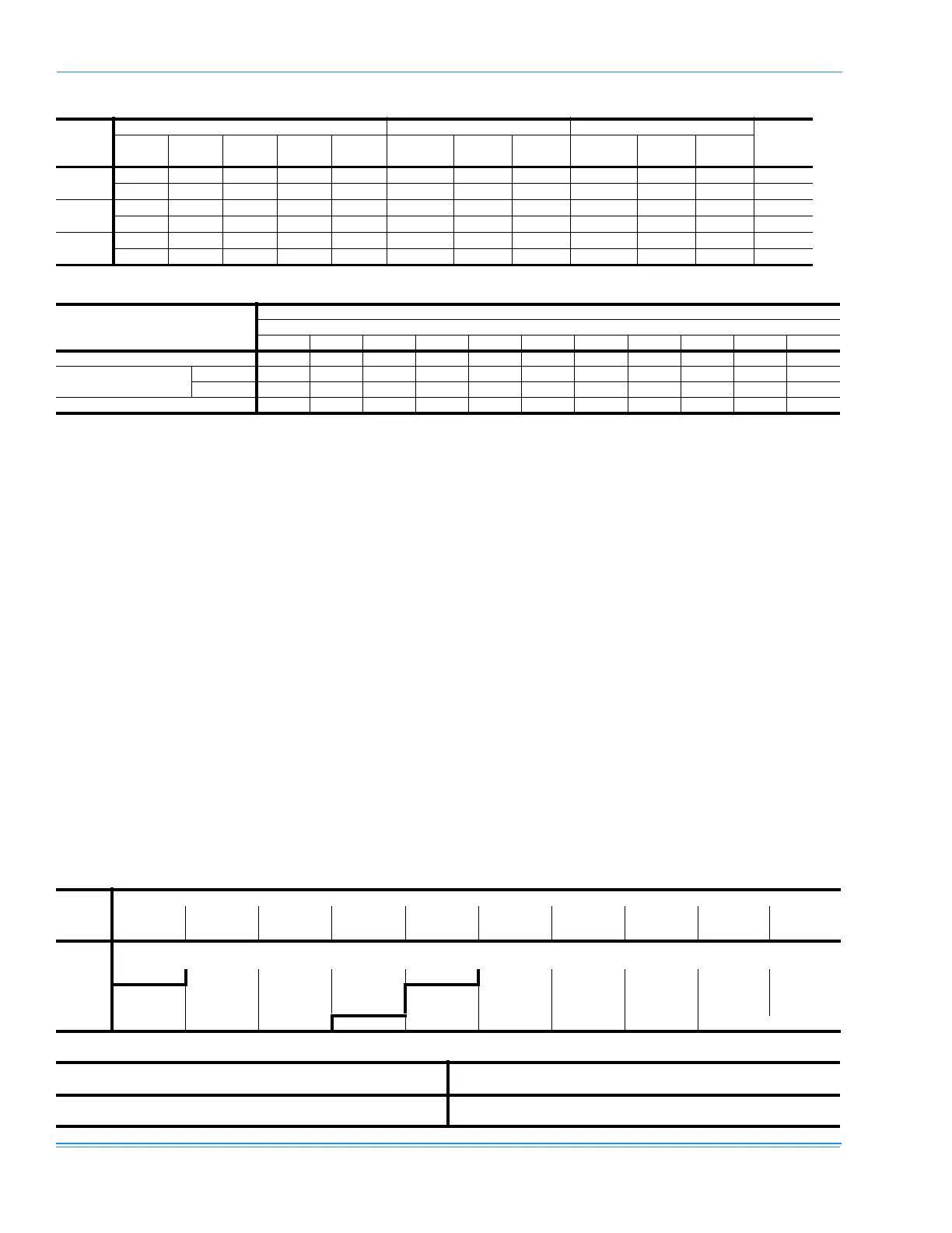
TABLE 30:STATIC RESISTANCES
DESCRIPTION
RESISTANCE, IWG
CFM
1000 1200 1400 1600 1800 2000 2200 2400 2600 2800 3000
ECONOMIZER
1,3
0.07 0.08 0.09 0.11 0.13 0.15 0.17 0.20 0.23 0.26 0.30
ELECTRIC
HEATERS
1
7-15KW0.040.050.060.070.080.100.120.140.160.190.22
20-30KW 0.06 0.07 0.08 0.09 0.11 0.13 0.15 0.17 0.20 0.23 0.26
COOLING ONLY
2
0.08 0.10 0.12 0.14 0.16 0.18 0.20 0.23 0.26 0.29 0.32
Example Supply Air Blower Performance
Air Flow
(CFM)
Available External Static Pressure - IWG
0.2 0.4 0.6 0.8 1.0 1.2 1.4 1.6 1.8 2.0
RPM BHP RPM BHP RPM BHP RPM BHP RPM BHP RPM BHP RPM BHP RPM BHP RPM BHP RPM BHP
Field Supplied
Drive
Standard Drive Option HIgh Static Drive Option
2000 907 1.00 990 1.07 1070 1.15 1146 1.23 1220 1.31 1291 1.40 1359 1.49 1425 1.58 1488 1.68 1550 1.77
2200 960 1.24 1043 1.31 1123 1.39 1199 1.47 1273 1.55 1344 1.64 1412 1.73 1478 1.82 1541 1.92 1602 2.01
2400 1015 1.51 1099 1.59 1178 1.66 1255 1.74 1329 1.83 1400 1.92 1468 2.01 1534 2.10 1597 2.19 1658 2.29
2600 1074 1.83 1157 1.90 1237 1.98 1314 2.06 1387 2.14 1458 2.23 - - - - ----
Table X: RPM Selection
Size
(Tons)
Model HP
Max
BHP
Motor
Sheave
Blower
Sheave
5 Turns
Open
4 Turns
Open
3 Turns
Open
2 Turns
Open
1 Turn
Open
Fully
Closed
XY
1.5 1.73 1VL44 AK56 930 995 1060 1130 1195 1260
2 2.3 1VP56 AK56 1325 1395 1460 1525 1590 1660