362247-BIM-B-0109
Johnson Controls Unitary Products 49
FLASH CODES
The UCB will initiate a flash code associated with
errors within the system. Refer to UNIT CONTROL
BOARD FLASH CODES Table 39.
RESETS
Remove the call for heating by lowering the thermostat
setting lower than the conditioned space temperature.
This resets any flash codes.
HEAT ANTICIPATOR SETPOINTS
It is important that the anticipator setpoint be correct.
Too high of a setting will result in longer heat cycles
and a greater temperature swing in the conditioned
space. Reducing the value below the correct setpoint
will give shorter “ON” cycles and may result in the low-
ering of the temperature within the conditioned space.
START-UP (COOLING)
PRESTART CHECK LIST
After installation has been completed:
1. Check the electrical supply voltage being supplied.
Be sure that it is the same as listed on the unit
nameplate.
2. Set the room thermostat to the off position.
3. Turn unit electrical power on.
4. Set the room thermostat fan switch to on.
5. Check indoor blower rotation.
• If blower rotation is in the wrong direction.
Refer to Phasing Section in general infor-
mation section.
• Check blower drive belt tension.
6. Check the unit supply air (CFM). See “CHECKING
SUPPLY AIR CFM” on page 42.
7. Measure evaporator fan motor's amp draw.
8. Set the room thermostat fan switch to off.
9. Turn unit electrical power off.
OPERATING INSTRUCTIONS
1. Turn unit electrical power on.
2. Set the room thermostat setting to lower than the
room temperature.
3. Compressor will energize after the built-in time
delay (five minutes).
POST START CHECK LIST
1. Verify proper system pressures.
2. Measure the temperature drop across the evapora-
tor coil.
3. Measure the system Amperage draw across all
legs of 3 phase power wires.
4. Measure the condenser fan amp draw.
SHUT DOWN
1. Set the thermostat to highest temperature setting.
2. Turn off the electrical power to the unit.
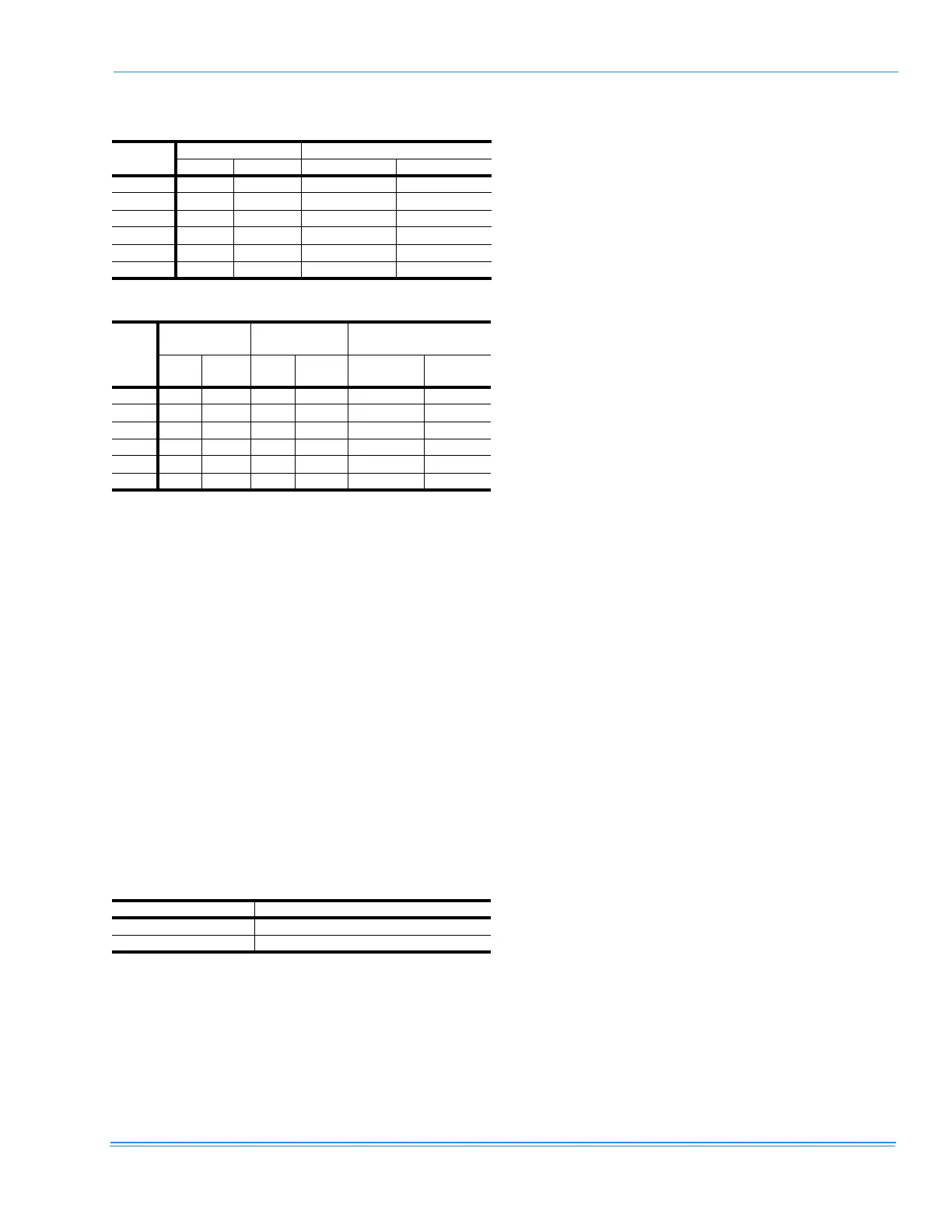
TABLE 33:SINGLE STAGE GAS HEAT LIMIT CONTROL
SETTING
Unit
(Tons)
Capacity, MBH Limit Control Opens, °F
Input Output Direct Drive Belt Drive
3 50 40 240 240
3 100 80 170 210
4 75 60 210 240
4 125 100 165 210
5 100 80 170 210
5 125 100 165 210
TABLE 34:2 STAGE GAS HEAT LIMIT CONTROL SETTING
Unit
(Tons)
1st Stage
Capacity
2nd Stage
Capacity
Limit Control Opens,
°F
Input
(MBH)
Output
(MBH)
Input
(MBH)
Output
(MBH)
Direct
Drive
Belt
Drive
3 45 36 75 61 210 240
3 69 55 115 92 200 200
4 45 36 75 61 210 240
4 75 60 125 101 165 210
5 45 36 75 61 210 210
5 75 60 125 101 165 210
TABLE 35:GAS HEAT ANTICIPATOR SETPOINTS
Gas Valve Anticipator Setpoint
Honeywell VR8204M 0.60 amp
White-Rodgers 36E36 0.54 amp