362247-BIM-B-0109
Johnson Controls Unitary Products 51
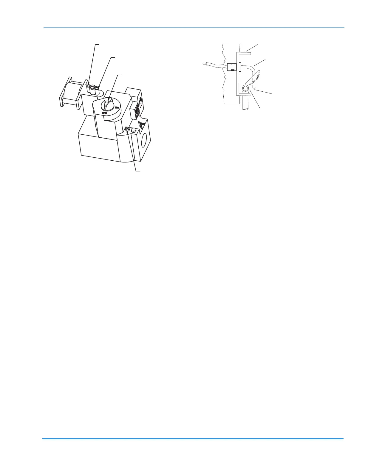
MANIFOLD GAS PRESSURE ADJUSTMENT
Adjustments to the high-fire and low-fire (2 stage) gas
flow may be made by turning the pressure regulator
adjusting screws on the automatic gas valve.
Adjust as follows:
1. Remove the adjustment screw cap(s) on the regu-
lator.
2. To decrease the gas pressure, turn the adjusting
screw counterclockwise.
3. To increase the gas pressure, turn the adjusting
screw clockwise.
4. Replace adjustment screw caps.
NOTE: The factory set high-fire manifold pressure for
these furnaces is 3.50 IWG. The actual mani-
fold pressure depends on the local fuel heating
value.
PILOT CHECKOUT
The pilot flame should envelope the end of the flame
sensor. To adjust pilot flame, (1) remove pilot adjust-
ment cover screw, (2) increase or decrease the clear-
ance for air to the desired level, (3) be sure to replace
cover screw after adjustment to prevent possible gas
leakage.
Put the system into operation and observe through
complete cycle to be sure all controls function properly.
BURNER INSTRUCTIONS
To check or change burners, pilot or orifices, CLOSE
MAIN MANUAL SHUT-OFF VALVE AND SHUT OFF
ALL ELECTRIC POWER TO THE UNIT.
1. Remove the screws holding either end of the mani-
fold to the burner supports.
2. Open the union fitting in the gas supply line just
upstream of the unit gas valve and downstream
from the main manual shut-off valve.
3. Remove the gas piping closure panel.
4. Disconnect wiring to the gas valves and spark ignit-
ors. Remove the manifold-burner gas valve
assembly by lifting up and pulling back.
FIGURE 20 - TYPICAL 2 STAGE GAS VALVES
REGULATOR ADJ. “HI”
(UNDER SCREW)
REGULATOR ADJ. “LO”
(UNDER SCREW)
“ON” - “OFF” CONTROL
PILOT ADJ.
(UNDER SCREW)
HONEYWELL
VR820RQ
FIGURE 21 - PROPER FLAME ADJUSTMENT
1 / 8 " G A P B E T W E E N C A R R Y - O V E R
T U B E A N D F L A M E S E N S O R B U L B
C A R R Y - O V E R T U B E
F L A M E S E N S O R B U L B
B U R N E R A S S E M B L Y B R A C K E T