362247-BIM-B-0109
8 Johnson Controls Unitary Products
LOCATION
Use the following guidelines to select a suitable loca-
tion for these units.
1. Unit is designed for outdoor installation only.
2. Condenser coils must have an unlimited supply of air.
3. Where a choice of location is possible, position the
unit on either north or east side of building.
4. For ground level installation, use a level concrete
slab with a minimum thickness of 4 inches. The
length and width should be at least 6 inches
greater than the unit base rails. Do not tie slab to
the building foundation.
5. Roof structures must be able to support the weight
of the unit and its options and/or accessories. Unit
must be installed on a solid level roof curb or
appropriate angle iron frame.
6. Maintain level tolerance to 1/2 inch maximum
across the entire length or width of the unit.
If a unit is to be installed on a roof curb or special frame
other than a UP roof curb, gasketing must be applied to
all surfaces that come in contact with the unit under-
side.
RIGGING AND HANDLING
Exercise care when moving the unit. Do not remove
any packaging until the unit is near the place of installa-
tion. Rig the unit by attaching chain or cable slings to
the lifting holes provided in the base rails. Spreader
bars, whose length exceeds the largest dimension
across the unit, MUST BE USED.
Units may also be moved or lifted with a forklift. Slotted
openings in the base rails are provided for this pur-
pose. Fork lengths must be a minimum of 42 inches.
Remove the nesting brackets from the four corners on
the top of the unit. All screws that are removed when
removing the brackets must be replaced on the unit.
Refer to Table 9 for unit weights and to the Figure 9 for
approximate center of gravity.
CLEARANCES
All units require certain clearances for proper operation
and service. Installer must make provisions for ade-
quate combustion and ventilation air in accordance with
Section 5.3, Air for Combustion and Ventilation of the
National Fuel Gas Code, ANSI Z223.1 (in U.S.A.) or
Sections 7.2, 7.3 or 7.4 of Gas Installation Codes CSA-
B149.1 (in Canada) and/or applicable provisions of the
local building codes. Refer to Dimensions and Clear-
ances shown in Figures 10 through 13 and Tables 18
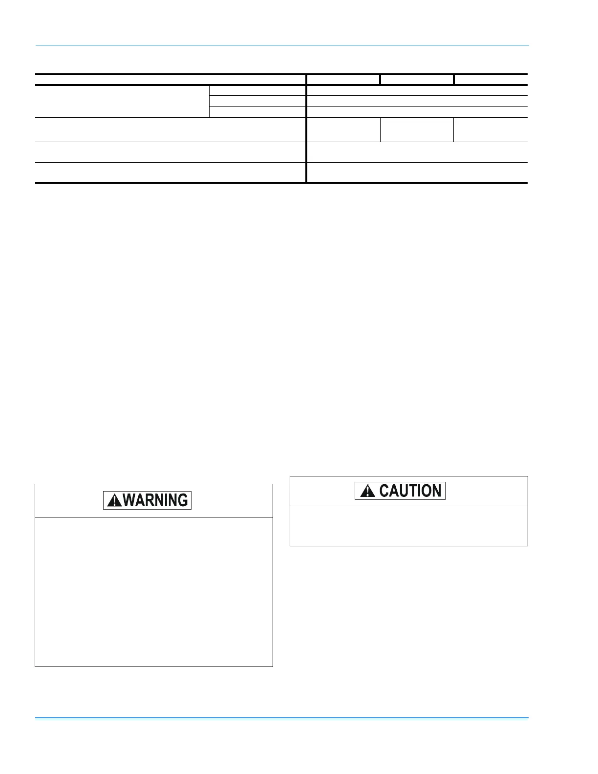
TABLE 1: UNIT APPLICATION DATA (DW)
UNIT MODEL NUMBER -03 -04 -05
Voltage Variation,
Min. / Max.
1
208/230 187 / 252
460 432 / 504
575 540 / 630
Supply Air CFM, Nom. 1200 1600 2000
Wet Bulb Temperature (ºF) of Air on Evaporator Coil,
Min. / Max
57 / 72
Dry Bulb Temperature (ºF) of Air on Condenser Coil,
Min. / Max.
0 / 125
1. Utilization range “A” in accordance with ARI Standard 110.
Excessive exposure of this furnace to contami-
nated combustion air may result in equipment
damage or personal injury. Typical contami-
nates include: permanent wave solutions, chlo-
rinated waxes and cleaners, chlorine based
swimming pool chemicals, water softening
chemicals, carbon tetrachloride, Halogen type
refrigerants, cleaning solvents (e.g. perchloro-
ethylene), printing inks, paint removers, var-
nishes, hydrochloric acid, cements and glues,
antistatic fabric softeners for clothes dryers,
masonry acid washing materials.
Before lifting a unit, make sure that all panels
are in place and that its weight is distributed
equally on all cables so it will lift evenly.