362247-BIM-B-0109
Johnson Controls Unitary Products 53
After the temperature rise has been determined, the
cfm can be calculated as follows:
After about 20 minutes of operation, determine the fur-
nace temperature rise. Take readings of both the return
air and the heated air in the ducts (about six feet from
the furnace) where they will not be affected by radiant
heat. Increase
the blower cfm to decrease the temper-
ature rise; decrease
the blower cfm to increase the
rise. Refer to the Blower Motor and Drive Data
Table 29.
TROUBLESHOOTING
COOLING TROUBLESHOOTING GUIDE
On calls for cooling, if the compressors are operating
but the supply air blower motor does not energize after
a short delay (the room thermostat fan switch is in the
“AUTO” position).
1. Turn the thermostat fan switch to the ON position.
If the supply air blower motor does not energize, go
to Step 3.
2. If the blower motor runs with the fan switch in the
ON position but will not run after the compressor
has energized when the fan switch is in the AUTO
position, check the room thermostat for contact
between R and G in the AUTO position during calls
for cooling.
3. If the supply air blower motor does not energize
when the fan switch is set to ON, check that line
voltage is being supplied to the contacts of the M2,
contactor, and that the contactor is pulled in. Check
for loose wiring between the contactor and the sup-
ply air blower motor.
4. If M2 is pulled in and voltage is supplied to M2,
lightly touch the supply air blower motor housing. If
it is hot, the motor may be off on internal protec-
tion. Cancel any thermostat calls and set the fan
switch to AUTO. Wait for the internal overload to
reset. Test again when cool.
5. If M2 is not pulled in, check for 24 volts at the M2
coil. If 24 volts are present at M2 but M2 is not
pulled in, replace the contactor.
6. Failing the above, if there is line voltage supplied at
M2, M2 is pulled in, and the supply air blower
motor still does not operate, replace the motor.
7. If 24 volts is not present at M2, check that 24 volts
is present at the UCB supply air blower motor ter-
minal, “FAN”. If 24 volts is present at the FAN,
check for loose wiring between the UCB and M2.
8. If 24 volts is not present at the “FAN” terminal,
check for 24 volts from the room thermostat. If 24
volts are not present from the room thermostat,
check for the following:
a. Proper operation of the room thermostat (contact
between R and G with the fan switch in the ON posi-
tion and in the AUTO position during operation calls).
b. Proper wiring between the room thermostat and the
UCB.
c. Loose wiring from the room thermostat to the UCB.
9. If 24 volts is present at the room thermostat but not
at the UCB, check for proper wiring between the
thermostat and the UCB, i.e. that the thermostat G
terminal is connected to the G terminal of the UCB,
and for loose wiring.
10. If the thermostat and UCB are properly wired,
replace the UCB.
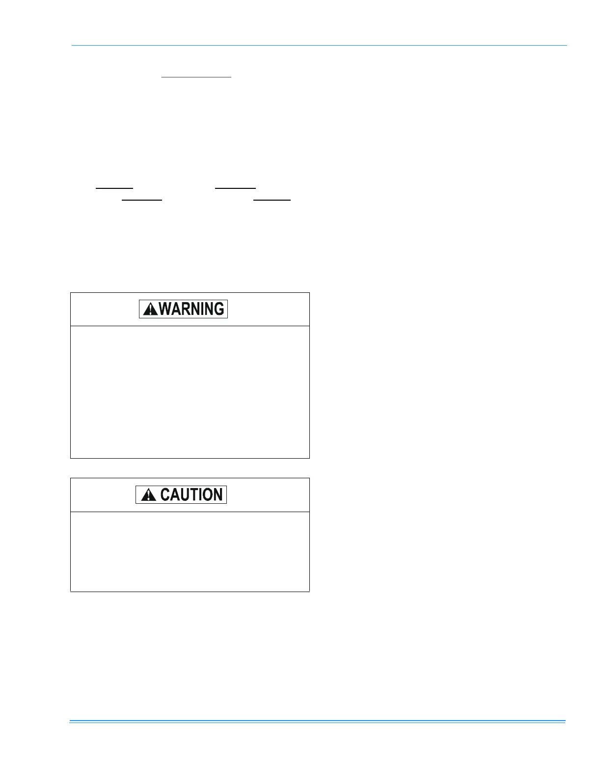
Troubleshooting of components may require
opening the electrical control box with the power
connected to the unit. Use extreme care when
working with live circuits! Check the unit
nameplate for the correct line voltage and set
the voltmeter to the correct range before making
any connections with line terminals.
Shut off all electric power to the unit prior to
any of the following maintenance procedures
to prevent personal injury.
Label all wires prior to disconnection when ser-
vicing controls. Wiring errors can cause
improper and dangerous operation, which
could cause injury to person and/or damage
unit components. Verify proper operation after
servicing.
CFM
Btuh Input x 0.8
=
108..xFTempRise
o