362247-BIM-B-0109
62 Johnson Controls Unitary Products
volts across terminals “MV” and “GROUND” termi-
nals. If no voltage detected, replace ignition con-
trol. If voltage is present, replace gas valve.
Main burners light but exhibit erratic flame characteristics.
1. Adjust air shutters as described in “BURNER AIR
SHUTTER ADJUSTMENT” on page 52.
2. Check the main burner orifices for obstruction and
alignment. Removal procedure is described in
BURNER INSTRUCTIONS on page 51. Clean or
replace burner orifices and burners as needed.
UNIT FLASH CODES
Various flash codes are utilized by the unit control
board (UCB) and the ignition control board (ICB) to aid
in troubleshooting. Flash codes are distinguished by
the short on and off cycle used (approximately 200ms
on and 200ms off). To show normal operation, the con-
trol boards flashes a 1 second on, 1 second off “heart-
beat” during normal operation. This is to verify that the
UCB and the ICB are functioning correctly. Do not con-
fuse this with an error flash code. To prevent confu-
sion, a 1-flash, flash code is not used.
Current alarms or active restrictions are flashed on the
UCB LED.
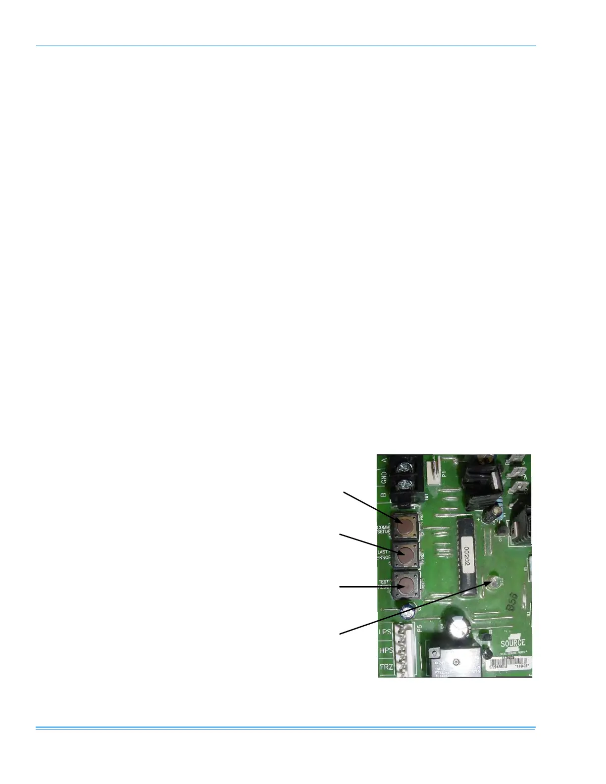
•
LAST ERROR - When this button is pressed
and released one time within five seconds, it
flashes the last five flash codes on the board’s
LED. The most recent alarm is shown first and
the oldest alarm is shown last.
When pressed and released twice within a five
second span, the fault history is cleared.
•
TEST RESET - When this button is pressed and
released one time within five seconds, any
anti-short cycle delays (ASCD) is by-passed
for one cycle.
When this button is pressed twice within five
seconds, any active lockouts are reset.
•
COMM SET UP - If the board is to be networked
with other units, this button is used to set the
network address.
The first time the button is pressed within five
seconds, it scans the bus, then assigns itself
the first available address {starts at 2}. It then
flashes that address one time.
Pressing the button two times within five sec-
onds causes the control to flash its address.
Pressing the button three times within five sec-
onds forces the control to reset its address to
1, which is the factory default.
Current alarms or active restrictions are flashed on the
ICB LED. No history is stored on the ICB.
FAN ON AND OFF DELAYS
The fan ON and OFF delays can be field adjusted by
pressing a combination of buttons on the UCB.
•
Gas Heat Option #1 - Press the LAST ERROR
and TEST RESET buttons simultaneously and
then release. The control flashes three times
as it writes a 30 second delay ON and a 90
second delay OFF to the program.
•
Gas Heat Option #2 - Press the COMM SETUP
and
TEST RESET buttons simultaneously and
then release. The control flashes four times as
it writes a 30 second delay ON and a 180 sec-
ond delay OFF to the program.
•
Electric Heat - Press and release the COMM
SETUP
and LAST ERROR buttons at the same
time. The control flashes twice on the LED as
the control writes a 0 second ON and a 30 sec-
ond OFF fan delay to the control’s program
memory.
FIGURE 26 - UNIT CONTROL BOARD
Comm Setup
Button
Last Error
Button
Test Reset
Button
ontrol Board
LED