362247-BIM-B-0109
Johnson Controls Unitary Products 9
and 19 for the clearances required for combustible con-
struction, servicing, and proper unit operation.
DUCTWORK
Ductwork should be designed and sized according to
the methods in Manual Q of the Air Conditioning Con-
tractors of America (ACCA).
A closed return duct system shall be used. This shall
not preclude use of economizers or outdoor fresh air
intake. The supply and return air duct connections at
the unit should be made with flexible joints to minimize
noise.
The supply and return air duct systems should be
designed for the CFM and static requirements of the
job. They should NOT be sized to match the dimen-
sions of the duct connections on the unit.
Refer to Figures 10 through 14 for information concern-
ing side and bottom supply and return air duct openings.
NOTE: It is recommended that, in Canada, the outlet
duct be provided with a removable access
panel. It is recommended that this opening be
accessible when the unit is installed in service,
and of a size such that smoke or reflected light
may be observed inside the casing to indicate
the presence of leaks in the heat exchanger.
The cover should be attached in a manner
adequate to prevent leakage.
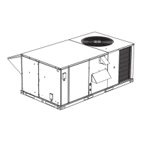
CONDENSATE DRAIN
Plumbing must conform to local codes. Use a sealing
compound on male pipe threads. Install a condensate
drain line from the 3/4” NPT female connection on the
unit to an open drain.
NOTE: The condensate drain operates in a negative
pressure in the cabinet. The condensate drain
line MUST be trapped to provide proper drain-
age. See Figure 1.
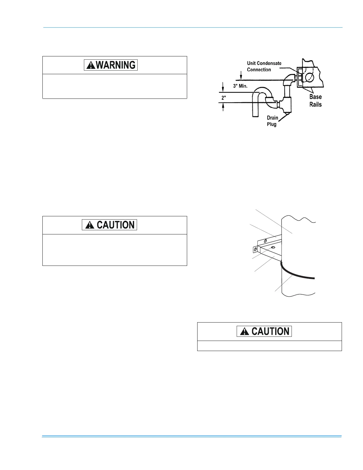
COMPRESSORS
Units are shipped with compressor mountings factory-
adjusted and ready for operation.
Units with scroll compressors have a shipping bracket
which must be removed after the unit is set in place.
See Figure 2.
FILTERS
One-inch or two-inch filters can be supplied with each
unit. Filters must always be installed ahead of the
evaporator coil and must be kept clean or replaced with
same size and type. Dirty filters will reduce the capacity
of the unit and will result in frosted coils or safety shut-
down. Minimum filter area and required sizes are
shown in Physical Data Table 8.
Do not permit overhanging structures or shrubs
to obstruct outdoor air discharge outlet, com-
bustion air inlet or vent outlets.
When fastening ductwork to side duct flanges
on unit, insert screws through duct flanges only.
DO NOT insert screws through casing. Outdoor
ductwork must be insulated and waterproofed.
FIGURE 1 - RECOMMENDED DRAIN PIPING
FIGURE 2 - COMPRESSOR RESTRAINING BRACKET
Do not loosen compressor mounting bolts.
WIRE TIE
(CUT AND
REMOVE)
MOUNTING
BRACKET TOP
(REMOVE)
MOUNTING
BRACKET BASE
REMOVE THESE
SCREWS (2)
COMPRESSOR