362247-BIM-B-0109
Johnson Controls Unitary Products 47
GAS HEATING SEQUENCE OF OPERATION
When there is a W1 call for heat, the heat relay (RW1)
is energized by the unit control board (UCB). The
RW1-1 contacts immediately close energizing the igni-
tion control board (ICB). The ICB checks the state of
the flame sense circuit, the roll out switch, the centrifu-
gal switch and the primary / auxiliary temperature limit
switch circuit. If they are in the expected state, then the
ICB energizes the draft motor and verifies that the cen-
trifugal switch located on the end of the draft motor
closes. After the centrifugal switch closes, a 15 second
heat exchanger purging period is completed. After this
purging period, the ICB will simultaneously energize
the pilot gas valve and the ignition coil. Once the flame
sensor senses a pilot flame is present, the ignition coil
is de-energized. The ICB checks for pilot flame stability
and once the ICB is satisfied that the pilot flame is sta-
ble, the main gas valve is energized by the ICB. The
UCB will energize the indoor blower after a 45 second
delay from the call for heat. The ICB and UCB both
monitor the furnace safety devices during the furnace
operation. When the call for heat is satisfied, the ICB
closes the pilot and main gas valves and performs a 30
second purging of the heat exchanger by continuing
the operation of the draft motor. The UCB continues
the operation of the indoor blower for a configurable
amount of time after the call for heat is satisfied.
TWO STAGE FURNACE ONLY
If a W1 only call for heat from a two stage thermostat is
present, then a two stage furnace will start on high fire
for 1 minute and then reduce to low fire until the call for
heat is satisfied or a W2 call for heat is received. If a
W2 call for heat is received while in low fire operation,
then the ICB will immediately move to high fire opera-
tion. If a W1 and W2 call for heat is present, then the
furnace will remain on high fire operation until the W2
call for heat is satisfied.
Automatic staging of a two stage furnace using a single
stage thermostat is possible. To achieve automatic
staging of a two stage furnace using a single stage
thermostat, cut the 440/GY wire that runs from pin 2 of
the S3 connector on the (UCB) unit control board to
P2-4 on the ignition control board. Cut the wire 1/2”
from the S3 mate-n-lock connector. Wire nut or tape off
the 1/2” wire. Attach the other end of the 440/GY wire
to the R terminal on the UCB, or to the TB1 power strip.
The unit will operate the same as a W1 only call for
heat for 10 minutes. If the call for heat is not satisfied in
the 10 minutes, then the ICB will move to high fire
operation until the W1 call for heat has been satisfied.
GAS HEAT OPERATION ERRORS
During furnace operation, the ICB monitors the flame
sense circuit, the centrifugal switch, the primary limit
switch and the roll out switch. If a signal from any of the
inputs moves to a fault state, then the ICB immediately
closes the pilot and main gas valves. The ICB will
determine the device that is signaling a fault and flash
a code for that device. A primary limit trip, centrifugal
switch trip or flame sense fault triggers a temporary
lock out. An auxiliary limit or a roll out switch trip
requires intervention to reset the ICB. The UCB also
monitors the primary limit and gas valve.
TABLE 32:ELECTRIC HEAT ANTICIPATOR SETPOINTS
HEATER
KW
VOLTAGE
SETTING, AMPS
TH1 TH2
5
230-3-60
0.35 -
70.35-
10 0.35 -
15 0.35 0.19
20 0.35 0.38
30 0.35 0.38
7
460-3-60
0.35 -
10 0.35 -
15 0.35 -
20 0.37 0.29
30 0.37 0.29
10
575-3-60
0.35 -
15 0.35 -
20 0.37 0.29
30 0.37 0.29
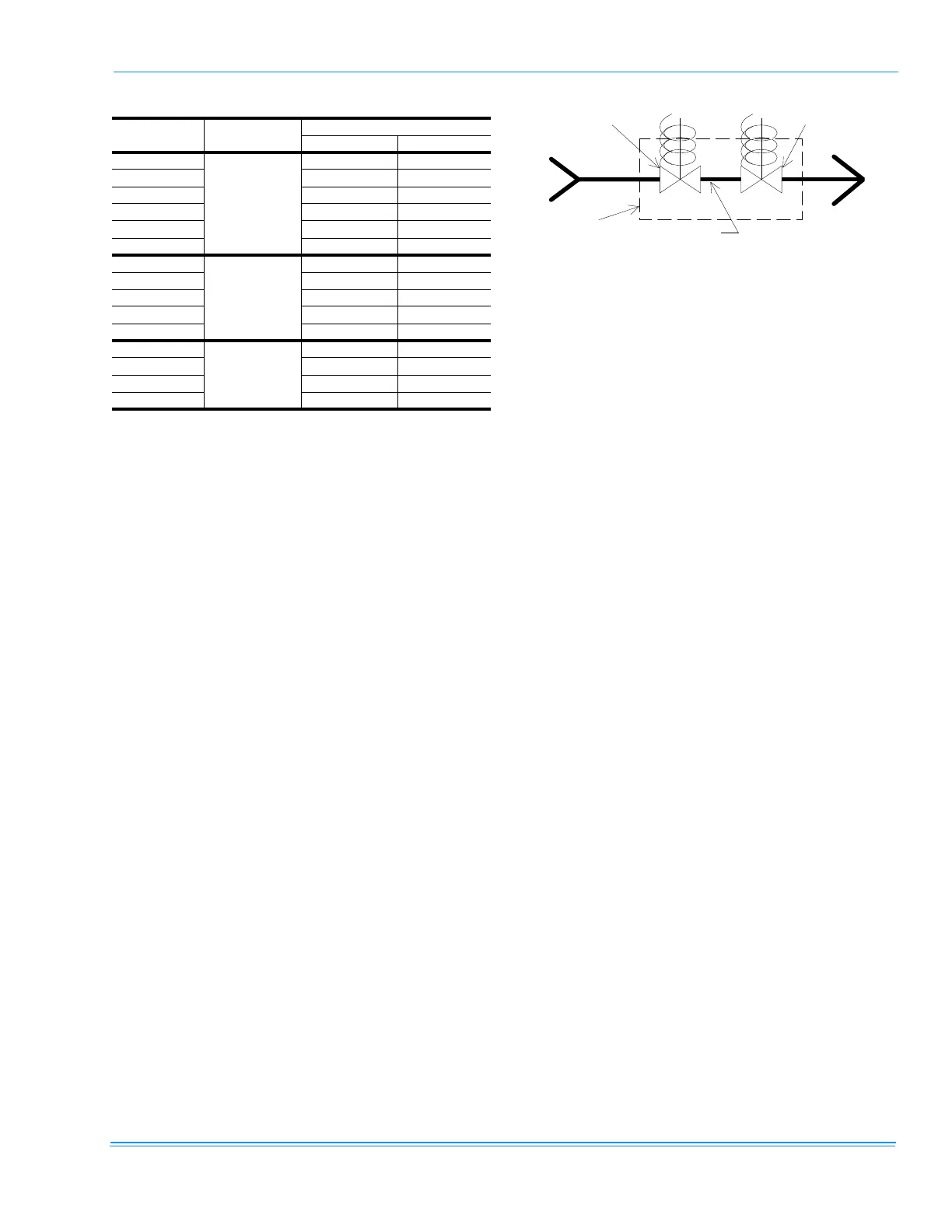
FIGURE 18 - GAS VALVE PIPING
GAS
VALVE
GAS MAIN
MAIN VALVE
TO MAIN
BURNER
REDUNDANT
VALVE
TO PILOT BURNER