RWB II ROTARY SCREW COMPRESSOR UNITS
INSTALLATION
070.200-IOM (DEC 11)
Page 11
OIL FILTER(S)
Use of filter elements other than
Frick may cause warranty claim
may to be denied.
The oil filter(s) and coalescer filter element(s) shipped with
the unit are best suited to ensure proper filtration and opera‑
tion of the system.
THERMOSYPHON OIL COOLING
Thermosyphon oil cooling is an economical, effective method
for cooling oil on screw compressor units. Ther mosyphon
cooling utilizes liquid refrigerant at condenser pressure and
temperature that is partially vaporized at the condenser tem‑
perature in a plate and shell vessel, cooling the oil to within
15°F of that temperature. The vapor, at condensing pressure,
is vented to the condenser inlet and reliquified. This method is
the most cost effective of all currently applied cooling systems
since no compres sor capacity is lost or compressor power
penalties in curred. The vapor from the cooler need only be
con densed, not compressed. Refrigerant flow to the cooler is
automatic, driven by the thermosyphon principle and cooling
flow increases as the oil inlet temperature rises.
EQUIPMENT ‑ The basic equipment required for a ther‑
mosyphon system consists of:
1. A source of liquid refrigerant at condensing pressure and
temperature, located in close proximity to the unit to mini mize
piping pressure drop. The liquid level in the refrigerant source
must be 6 to 8 feet minimum above the center of the oil cooler.
2. A plate and shell oil cooler with:
Plate Side: Oil 400 psi design
Shell Side: Refrigerant 400 psi design
Due to the many variations in refrigeration system design
and physical layout, several systems for assuring the above
criteria are possible.
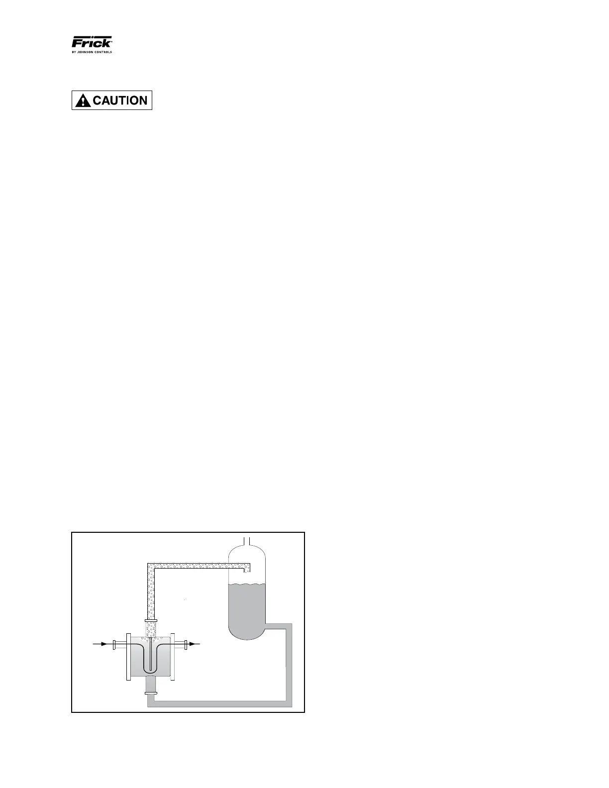
SYSTEM OPERATION ‑ Liquid refrigerant fills the cooler
shell side up to the Thermosyphon receiver liquid level. See
Figure 7.
Hot oil (above the liquid temperature) flowing through the
cooler will cause some of the refrigerant to boil and vaporize.
The vapor rises in the return line. The density of the refriger‑
ant liquid/vapor mixture in the return line is considerably less
than the density of the liquid in the supply line. This imbalance
provides a differential pressure that sustains a flow condi tion
to the oil cooler. This relationship involves:
1. Liquid height above the cooler.
2. Oil heat of rejection.
3. Cooler size and piping pressure drops.
Current thermosyphon systems are using two‑pass oil cool‑
ers and flow rates based on 3:1 overfeed.
The liquid/vapor returned from the cooler is separated in the
receiver. The vapor is vented to the condenser inlet and need
only be reliquified since it is still at condenser pressure.
OIL TEMPERATURE CONTROL ‑ Oil temperature will gen‑
erally run about 15 ‑ 35°F above condensing tempera ture.
In many cases, an oil temperature control is not required if
condensing temperature is above 65°F as oil tempera ture
can be allowed to float with condenser temperature.
Condensing Temperature: 65°F ‑ 105°F
Oil Temperature: 80°F ‑ 140°F
INSTALLATION ‑ The plate and shell type thermosyphon oil
cooler with oil‑side piping and a thermostatically controlled
mixing valve (if ordered) are factory mount ed and piped. The
customer must supply and install all piping and equip ment
located outside of the shaded area on the piping diagram
with consideration given to the following:
1. The refrigerant source, thermosyphon or system receiv er,
should be in close proximity to the unit to minimize piping
pressure drop.
2. The liquid level in the refrigerant source must be 6 to 8
feet minimum above the center of the oil cooler.
3. A safety valve should be installed if refrigerant isolation
valves are used for the oil cooler.
The component and piping arrangement shown in Figure 8, is
intended only to illustrate the operating principles of thermo‑
syphon oil cooling. Other component layouts may be better
suited to a specific installation. Refer to publication 070.900‑E
for additional information on Thermosyphon Oil Cooling.
HOT OIL IN
FROM
SEPARATOR
120-140 F
OIL OUT
O
TO SYSTEM CONDENSER
95 F
2.5#/FT
O
3
95 F
36#/FT
O
3
TS RECEIVER
Figure 7